3.2 Wiring for main circuit terminals and grounding terminals
Table 3.1 shows the main circuit power terminals and grounding terminals.
Table 3.1 Symbols, Names and Functions of the Main Circuit Power Terminals
Symbol Name Functions
L1/R, L2/S, L3/T
or L1/L, L2/N
Main circuit power
inputs
Connect the three-phase input power lines or single-phase input power lines
U, V, W Inverter outputs Connect a three-phase motor.
P1, P(+) DC reactor
connection
Connect an optional DC reactor (DCRE) for improving power factor.
P(+), DB DC braking resistor Connect an optional braking resistor.
P(+), N(-) DC link bus Connect a DC link bus of other inverter(s). An optional regenerative converter is also connectable to
these terminals.
G
Grounding for
inverter and motor
Grounding terminals for the inverter’s chassis (or case) and motor. Earth one of the terminals and
connect the grounding terminal of the motor. Inverters provide a pair of grounding terminals that
function equivalently.
3.3 Wiring for control circuit terminals
Table 3.2 lists the symbols, names and functions of the control circuit terminals. The wiring to the control circuit terminals differs
depending upon the setting of the function codes, which reflects the use of the inverter. Route wires properly to reduce the influence of
noise.
Table 3.2 Symbols, Names and Functions of the Control Circuit Terminals
Classifi-
cation
Symbol Name Functions
[13] Power
supply
for the
potentio-
meter
Power supply (+10 VDC) for frequency command potentiometer
(Potentiometer: 1 to 5kΩ)
The potentiometer of 1/2 W rating or more should be connected.
[12] Analogue
setting
voltage
input
(1) The frequency is commanded according to the external analogue input voltage.
• 0 to ±10 VDC/0 to ±100% (Normal operation)
• ±10 to 0 VDC/0 to ±100% (Inverse operation)
(2) Inputs setting signal (PID command value) or feedback signal.
(3) Used as additional auxiliary setting to various frequency settings.
• Input impedance: 22kΩ
• The maximum input is +15 VDC, however, the current larger than
±10 VDC is handled as ±10 VDC.
Note: Inputting a bipolar analogue voltage (0 to ±10VDC) to terminal [12] requires setting function code C35 to "0."
Analogue
setting
current
input
(C1
function)
(1) The frequency is commanded according to the external analogue input current.
• 4 to 20 mA DC/0 to 100% (Normal operation)
• 20 to 4 mA DC/0 to 100 % (Inverse operation)
(2) Inputs setting signal (PID command value) or feedback signal.
(3) Used as additional auxiliary setting to various frequency settings.
• Input impedance: 250Ω
• Maximum input is +30 mA DC; however, the current larger than +20 mA DC is handled as +20 mA DC.
Analogue
setting
voltage
input
(V2
function)
(1) The frequency is controlled according to the external analogue input voltage.
• 0 to +10 VDC/0 to +100 % (Normal operation)
• +10 to 0 VDC/0 to +100 % (Inverse operation)
(2) Inputs setting signal (PID command value) or feedback signal.
(3) Used as additional auxiliary setting to various frequency settings.
• Input impedance: 22 kΩ
• Maximum input is +15 VDC; however, the voltage larger than +10 VDC is handled as +10 VDC.
PTC
thermistor
input
(PTC
function)
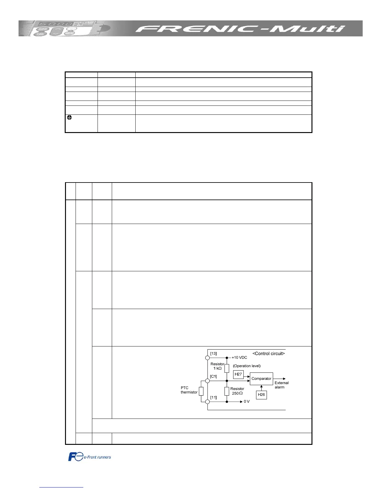
(1) Connects PTC
(Positive Temperature
Coefficient) thermistor
for motor protection.
The figure shown
below illustrates the
internal circuit
diagram. To use the
PTC thermistor, you
must change data of
the function code H26.
Figure 3.6 Internal Circuit Diagram
[C1]
The C1 function, V2 function, or PTC function can be assigned to terminal [C1]. Doing so requires setting the slide switch on the
interface PCB and configuring the related function code. For details, refer to Section 3.5, "Setting up the slide switches".
Analogue input
[11] Analogue
common
Common for analogue input/output signals ([13], [12], [C1], and [FM])
Isolated from terminals [CM]s and [CMY].

 Loading...


