12
Hb Heater Break Alarm Setpoint: If the heater’s operating
current falls below this setpoint, the heater break
alarm output relay is energized. This option is used in
cases where the PXW is controlling a bank of heaters
wired in parallel. A current transformer around the hot
lead going to the heater bank and connected to the
controller is tied with the controller’s output and sens-
es the current used by the heater bank. If one or more
of the zones burnout, resulting in cold spots, the cur-
rent used by the defective heater bank is reduced. By
determining what the optimal current and the optimal
current minus one zone for the heater bank is, the
Heater Break Alarm setpoint can be calculated and
entered.
Setting Range: 0.0 to 50.0 amps.
Not indicated without the Heater Break Alarm option.
Not available on PXW4, or with 4-20 mA DC outputs.
Detection is made only on a single-phase heater. This
function cannot be used when controlling a heater
with SCR phase-angle control.
Cycle Time, “TC,” must be set at 6 secs. or higher.
AT Autotuning: Autotuning is the automatic calculation
and entering of the control parameters (P, I and D) into
memory. Autotuning will also automatically set anti-
reset wind-up (Ar).There are two types of Autotuning
that can be performed by the controller, Autotuning at
main setpoint or Autotuning at 10% of full scale below
main setpoint. The latter may yield slightly different val-
ues, not as precise, but the process overshoot encoun-
tered during the autotuning procedure would not be as
much. Enter the value for the type of autotuning you
would like to run on your particular application based
on overshoot tolerances and the precision of the PID
parameters needed. For more information on principles
of Autotuning, refer to Appendix A.
0 - Autotuning off
1 - Autotuning performed at setpoint
2 - Autotuning performed at 10% of F.S. below setpoint
LoC Lock-out: This function enables or disables changing
the settings of parameters.
Code:
0 - All parameter settings are changeable
1 - All parameter settings are locked; cannot be
changed
2 - Only the main setpoint can be changed; all other
parameter settings are locked and cannot be changed.
SECONDARY (SYSTEM) MENU
P Proportional Band: The proportional band is that area
around main setpoint where the control output is nei-
ther fully on nor fully off.
Setting range: 0.0 to 999.9% of full scale
For On/Off control, set to “0”
I Integral Time (reset): The Integral Time is the speed at
which a corrective increase or decrease in output is
made to compensate for offset which usually accom-
panies proportional only processes. The more Integral
Time entered, the slower the action. The less Integral
Time entered, the faster the action. Enter a value that
would eliminate offset without overcompensating,
leading to process oscillation.
Setting Range: 0 to 3200 secs
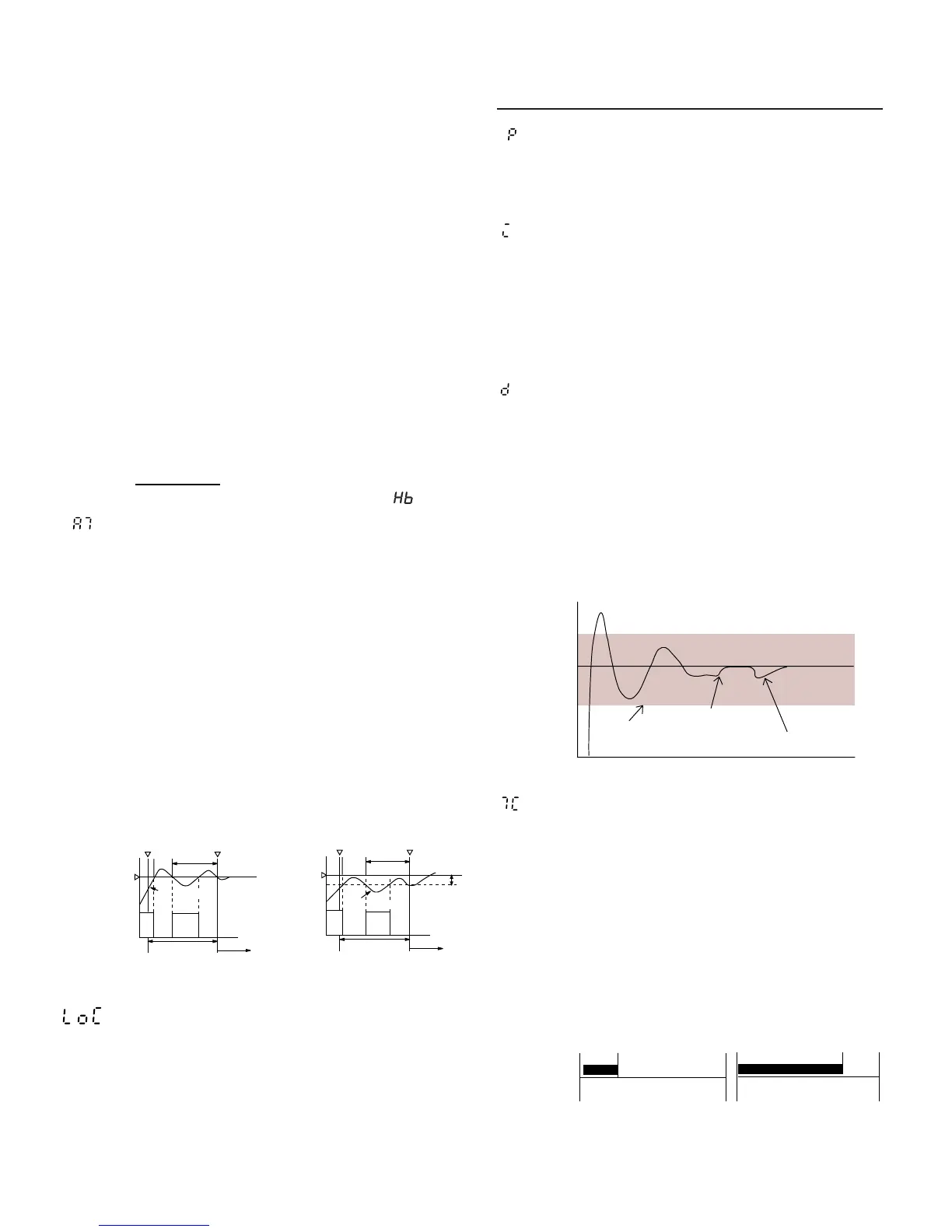
d Derivative Time (Rate): The Derivative Time is that time
used in calculating rate of change and thermal lag in
helping eliminate overshoot which results in response
to process upsets. This overshoot usually accompanies
proportional only and proportional-integral processes.
The derivative action dampens proportional and inte-
gral action as it anticipates where the process should
be. The more Derivative Time entered, the more damp-
ing action. The less Derivative Time entered, the less
damping action. Enter as much Derivative Time as nec-
essary to eliminate overshoot without over-damping
the process resulting in process oscillation.
Setting Range: 0.0 to 999.9 secs
TC Cycle Time (Output #1): The Cycle Time for output #1 is
that time where the output is on for a percentage of
that time and off for a percentage of that time, creating
a proportioning effect. The Cycle Time is only used
when P, PI, PD, or PID control action is used, and when
the output is time proportional as with the relay or SSR
driver outputs. The shorter the Cycle Time, the higher
the proportioning resolution is, and better is the con-
trol, but there will be an increased strain on the output
device. Enter a value that is based on the limitations of
your controller’s output type.
Setting range: 1 to 150 secs.
For relay output: Set to 30 secs. or more.
For SSR/SSC driver output: Set to 1 sec or more.
For current output: Set to 0 (normally not indicated)

 Loading...


