10
Refer to parameter “P-n1” and to the Table of Output Type Codes to
choose the preferred type of control action– reverse acting or direct
acting.
If using two outputs in a heat/cool type control, please refer to
Appendix D for more details.
Relay
• Connecting a load to full capacity of the relay will shorten the relay
life, especially if it is operated at a rapid rate. To protect the output
relay, an external relay or a contactor should be used. If a higher
current rating is required, a solid-state relay driver type output is
recommended.
• Connect the load between the normally opened contacts of the
relay.This way, if power to the controller is disrupted, the output cir-
cuit would open, preventing the load from running out of control.
• Set the proportional time cycle parameter, “TC” to 30 secs. or more.
• Use of “Z-trap” (manufacturer: Fuji Electric Co.) is recommended to
protect the relay against switching surges and to ensure the prod-
uct’s long life. Connect it between the contacts of the relay as
shown in the example below.
Part No.: ENC241D-05A (power supply voltage: 100V)
ENC471D-05A (power supply voltage: 200V)
SSR/SSC Driver (Pulsed DC Voltage)
• The non-isolated DC output is used to drive an external load-han-
dling device such as Solid-State Relay(SSR) or Solid-State
Contactor(SSC).
• The total current drawn, for both single and dual outputs, should be
within the allowed value.
• Make sure the polarity is correct.
• Set the proportional time cycle parameter, “TC” to 1 sec. or more.
4 to 20mA DC
• The output is a non-isolated analog signal used to drive a variety of
output devices such as SCRs and valve actuators.
• The load resistance must be less than 600Ω.
• Make sure the polarity is correct.
• The proportional time cycle parameter, “TC” is set to 0, and is not
displayed on the programming menu.
Wiring Alarms
• Make sure the load does not exceed the rated capacity of the relay.
• Several types of alarm configurations can be programmed and does
not require a change in the wiring. Refer to parameters AL, AH, P-
AH, P-AL, P-An.
• For details on Heater Break alarm, please refer to Appendix D and
the Heater Break Alarm Setpoint parameter “Hb” in the program-
ming section.
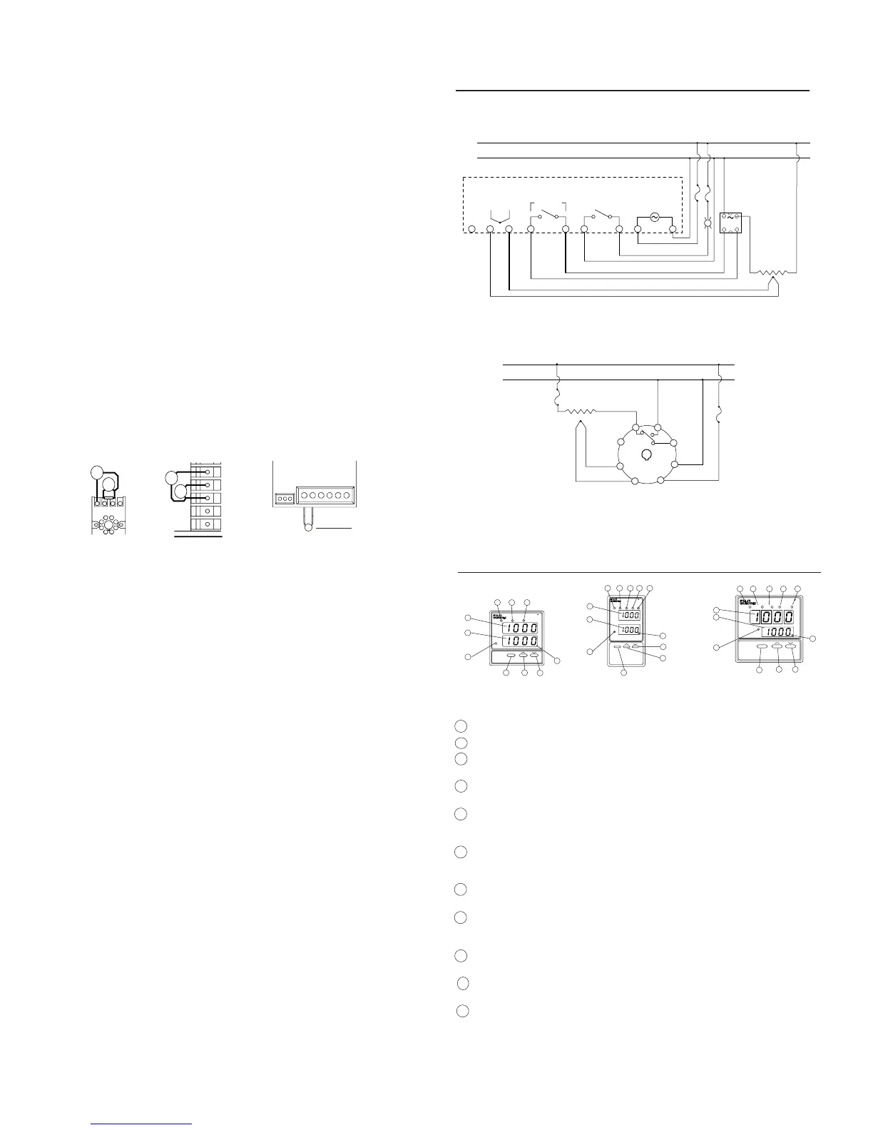
SYSTEM WIRING DIAGRAMS
Name Function
1 Process Value (PV) display Displays the process value (PV).
2 Set value (SV) indication lamp Stays on while a set value is on the display.
3 Set value (SV) and Displays set value (SV), or parameter symbol or
parameter display code when setting various parameters.
4 SELECT key Key for switching between the parameter blocks
and for scrolling within the block.
5 UP key For incrementing the numerical value or scrolling
up the the menu. Numerical value changes contin-
uously when held pressed.
6 DOWN key For decrementing the numerical value or scrolling
down the menu. Numerical value is decremented
continuously when held pressed.
7 Auto-tuning indicator The indicator blinks while the PID auto-tuning is
being performed.
8 Control Output indication lamp C: (for PXW4) Stays on while control output is ON.
C1: Stays on while control output 1 is ON.
C2: Stays on while control output 2 is ON.
9 Upper limit alarm Comes on when the upper limit alarm is activated.
indication lamp (optional) Blinks while the alarm value is being set.
10 Lower limit alarm Comes on when the lower limit alarm is activated.
indication lamp (optional) Blinks while the alarm value is being set.
11 Heater break alarm Comes on when the heater break alarm is output.
indication lamp

 Loading...


