En-11
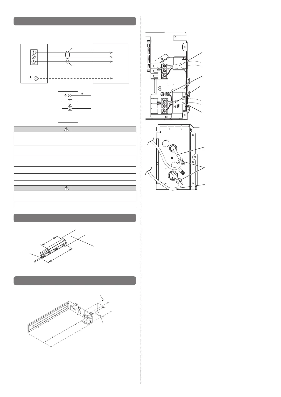
6.1. Wiring system diagram
ConnectioncabletooutdoorunitorBRANCHBOX
INDOORUNIT
OUTDOORUNITor
BRANCHBOX
TERMINAL
Type60245IEC57
Cablesize1.5mm
2
(Inter-unit)
Powerlines
Groundingline
Powerline
Controlline
Pleaseconnectitto
thespeciedterminal.
Wired remote controller cable
*Groundtheremotecontroller
(Pleaseconnectitwhennecessary.)
Red
White
Black
Indoor
unit side
CAUTION
Tighten the indoor unit connection cable and power supply indoor and outdoor unit,
branch box terminal board connections rmly with the terminal board screws.Faulty
connectionmaycauseare.
If the indoor unit connection cable and power supply are wired incorrectly, the air
conditioner may be damaged.
Connect the indoor unit connection cable by matching the numbers of the outdoor,
branch box and indoor units terminal board numbers as shown in terminal label.
Earth both the indoor and outdoor, branch box units by attaching a earth cable.
Unitshallbegroundedincompliancewiththeapplicablelocalandnationalcables.
CAUTION
Besuretorefertotheabovediagramfordocorrecteldwiring.Wrongwiringcauses
malfunction of the unit.
Checklocalelectricalrulesandalsoanyspecicwiringinstructionsorlimitation.
6.2. Connection cable preparation
Keep the earth wire longer than the other wires.
Powersupplycable
or connection cable
20mm
30mmormore
Earth wire
•Usea4-corewirecable.
6.3. Connection of wiring
(1) Removethecontrolboxcoverfromthecontrolbox.
Screw
Controlboxcover
Removethe4screws
and remove the control
box cover from the
control box.
(2) Cableconnection
• Connect the connection cable to the terminal board.
• Connecttheremotecontrollercabletotheterminalboard.
• Fixtheremotecontrollercabletothecontrolboxcoverwithanylonclamp.
Remote controller cable
1:Red
2:White
3:Black
Earth
Binder(Medium)
(Accessories)
Powersupplycable
Binder(Medium)
(Accessories)
Remote controller cable
Powersupplycable
9374815173-04_IM.indb 11 9/21/2011 1:45:24 PM
 Loading...