En-7
4.2. Pipe requirement
CAUTION
• Referto the Installation Manualof the outdoor unitfor description of thelength of
connecting pipe or for difference of its elevation.
• Usepipewithwater-resistantheatinsulation.
CAUTION
• Install heat insulation around both the gas and liquid pipes. Failure to do so may
cause water leaks.
Useheatinsulationwithheatresistanceabove120°C.(Reversecyclemodelonly)
In addition, if the humidity level at the installation location of the refrigerant piping is
expectedtoexceed70%,installheatinsulationaroundtherefrigerantpiping.Ifthe
expectedhumiditylevelis70-80%,useheatinsulationthatis15mmorthickerand
iftheexpectedhumidityexceeds80%,useheatinsulationthatis20mmorthicker.
Ifheatinsulationisusedthatisnotasthickasspecied,condensationmayformon
the surface of the insulation. In addition, use heat insulation with heat conductivity of
0.045W/(m·K)orless(at20°C).
4.3. Flare connection (Pipe connection)
WARNING
• Tightenthe are nuts with a torque wrench using the specied tighteningmethod.
Otherwise,thearenutscouldbreakafteraprolongedperiod,causingrefrigerantto
leakandgenerateahazardousgasiftherefrigerantcomesintocontactwithaame.
4.3.1. Flaring
• UsespecialpipecutterandaretoolexclusiveforR410A.
(1)
Cuttheconnectionpipetothenecessarylengthwithapipecutter.
(2)
Hold the pipe downward so that cuttings will not enter thepipe and remove any
burrs.
(3)
Insertthearenut(alwaysusethearenutattachedtotheindoorandoutdoorunits
respectively)ontothepipeandperformtheareprocessingwithaaretool.Use
thespecialR410Aaretool,orthe conventionalaretool. Leakageofrefrigerant
mayresultifotherarenutsareused.
(4)
Protectthepipesbypinchingthemorwithtapetopreventdust,dirt,orwaterfrom
entering the pipes.
Die
Pipe
A
B
Checkif[L]isareduniformly
and is not cracked or scratched.
Pipe outside diameter
[mm (in.)]
Dimension A [mm]
Dimension B
-
0
0.4
[mm]
Flare tool for R410A,
clutch type
6.35(1/4)
0to0.5
9.1
9.52(3/8) 13.2
12.70(1/2) 16.6
15.88(5/8) 19.7
19.05(3/4) 24.0
Whenusing conventional are tools to are R410Apipes, the dimensionAshould be
approximately0.5mmmorethanindicatedinthetable(foraringwithR410Aaretools)
toachievethespeciedaring.UseathicknessgaugetomeasurethedimensionA.
Width across
ats
Pipe outside
diameter [mm (in.)]
Width across flats
of Flare nut [mm]
6.35(1/4) 17
9.52(3/8) 22
12.70(1/2) 26
15.88(5/8) 29
19.05(3/4) 36
4.3.2. Bending pipes
•
If pipes are shaped by hand, be careful not to collapse them.
•
Donotbendthepipesinananglemorethan90°.
•
When pipes are repeatedly bend or stretched, the material will harden, making it
difculttobendorstretchthemanymore.
•
Do not bend or stretch the pipes more than 3 times.
CAUTION
• To prevent breaking of the pipe, avoid sharp bends.
• If the pipe is bent repeatedly at the same place, it will break.
4.3.3. Pipe connection
CAUTION
• Be sure to install the pipe against the port on the indoor unit correctly. If the centering
isimproper,thearenutcannottightensmoothly.Ifthearenutisforcedtoturn,the
threads will be damaged.
• Do not removethe flare nut fromthe indoor unit pipe until immediatelybefore
connecting the connection pipe.
• Holdthetorquewrenchatitsgrip,keepingitatarightanglewiththepipe,inorderto
tightenthearenutcorrectly.
• Tightentheare nutswith a torquewrench using thespecied tightening method.
Otherwise,thearenutscouldbreakafteraprolongedperiod,causingrefrigerantto
leakandgenerateahazardousgasiftherefrigerantcomesintocontactwithaame.
• Connectthepipingsothatthecontrolboxcovercaneasilyberemovedforservicing
when necessary.
• Inordertopreventwaterfromleakingintothecontrolbox,makesurethatthepiping
is well insulated.
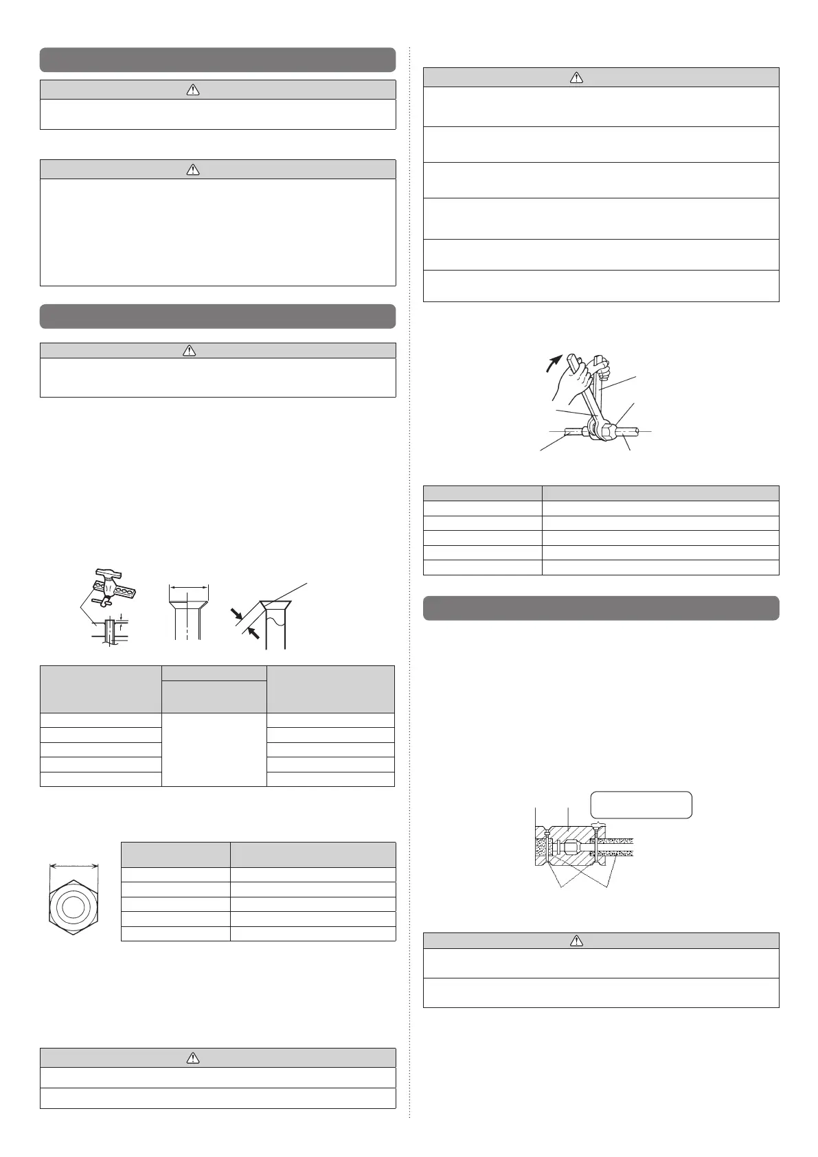
Whenthearenutistightenedproperlybyyourhand,holdthebodysidecouplingwith
aseparatespanner,thentightenwithatorquewrench.(Seethetablebelowfortheare
nuttighteningtorques.)
Tighten with 2 wrenches.
Holdingwrench
Flare nut
Connectionpipe
Torque wrench
Indoor unit pipe
(Bodyside)
Flare nut [mm (in.)] Tightening torque [N·m (kgf·cm)]
6.35(1/4)dia. 16to18(160to180)
9.52(3/8)dia. 32to42(320to420)
12.70(1/2)dia. 49to61(490to610)
15.88(5/8)dia. 63to75(630to750)
19.05(3/4)dia. 90to110(900to1,100)
4.4. Installing heat insulation
Install the heat insulation material after performing a refrigerant leak check (see the
InstallationManualfortheoutdoorunitfordetails).
4.4.1. COUPLER HEAT INSULATION
• Insulatewiththecouplerheatinsulation(Accessories)aroundthegaspipeandliquid
pipe at indoor unit.
• Afterinstallingthecouplerheatinsulation,wrapbothendswithvinyltapesothat
there is no gap.
• Afterafxingthecouplerheatinsulation,secureitwith2binders(large),oneoneach
end of the insulation.
• Makesurethatthebindersoverlaptheheatinsulationpipe.
Couplerheat
insulation
(Accessories)
Coverthisportionwith
heat insulation.
Binder(Large)
(Accessories)
Heatinsulation
CAUTION
• Afterchecking for gas leaks (refer to the Installation Manual of the outdoor unit),
perform this section.
• Installheatinsulationaroundboththelarge(gas)andsmall(liquid)pipes.Failureto
do so may cause water leaks.
9374815173-04_IM.indb 7 9/21/2011 1:45:21 PM
 Loading...