En-5
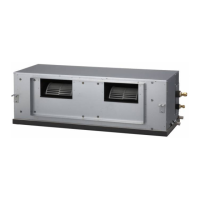
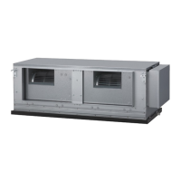
3.3B. Install the unit (Wall mounted type/ Floor standing
concealed type)
WARNING
• Install the air conditioner in a location which can withstand a load doat least 5
times the weight of the main unit and which will not amplify sound or vibration. If the
installation location is not strong enough, the indoor unit may fall and cause injuries.
• If the job is done with the panel frame only, there is a risk that the unitwill come
loose.Pleasetakecare.
3.3B.1. UNIT INSTALLATION EXAMPLE
(Wall mounted type/Floor standing concealed type)
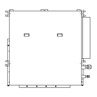
Connectthelocallypurchasedduct.
(1)Inletside
• Connecttheducttothelocallypurchasedinletange.
• Connecttheangetothebodywiththelocallypurchasedtappingscrews.
• Windtheinletangeconnectingtotheductwiththealuminumtapeetc.toavoidthe
air leakage.
CAUTION
• Whentheductisconnectedtoinletside,removecontainedlterandsurelyattach
locallypurchasedlteratinletopening.
(2)Outletside
• Connecttheductwithadjustinginsideofoutletange.
• Windtheoutletangeconnectingtotheductwiththealuminumtapeetc.toavoidthe
air discharge.
• Insulatetheducttoavoidthedewcondensation.
CAUTION
• Check that duct work doesnot exceed the rangeof externalstaticpressure of
equipment.
• Makesuretoinsulateductstoavoidthedewcondensation.
• Makesuretoinsulatebetweenductsandwallsifmetalductsareused.
• Pleaseexplainhandlingandwashingmethodsoflocallypurchasedmaterialstothe
customer.
• Topreventpeoplefromtouchingthepartsinsidetheunit,besuretoinstallgrilleson
the inlet and outlet ports. The grilles must be designed in such a way that cannot be
removed without tools.
• Whenconnectingtheducttotheoutletportoftheindoorunit,besuretoinsulatethe
outlet port and the installation screws to prevent water from leaking around the port.
• Set the static pressure outside the unit to 90Pa or less (the allowable range is
between0and90Pa).
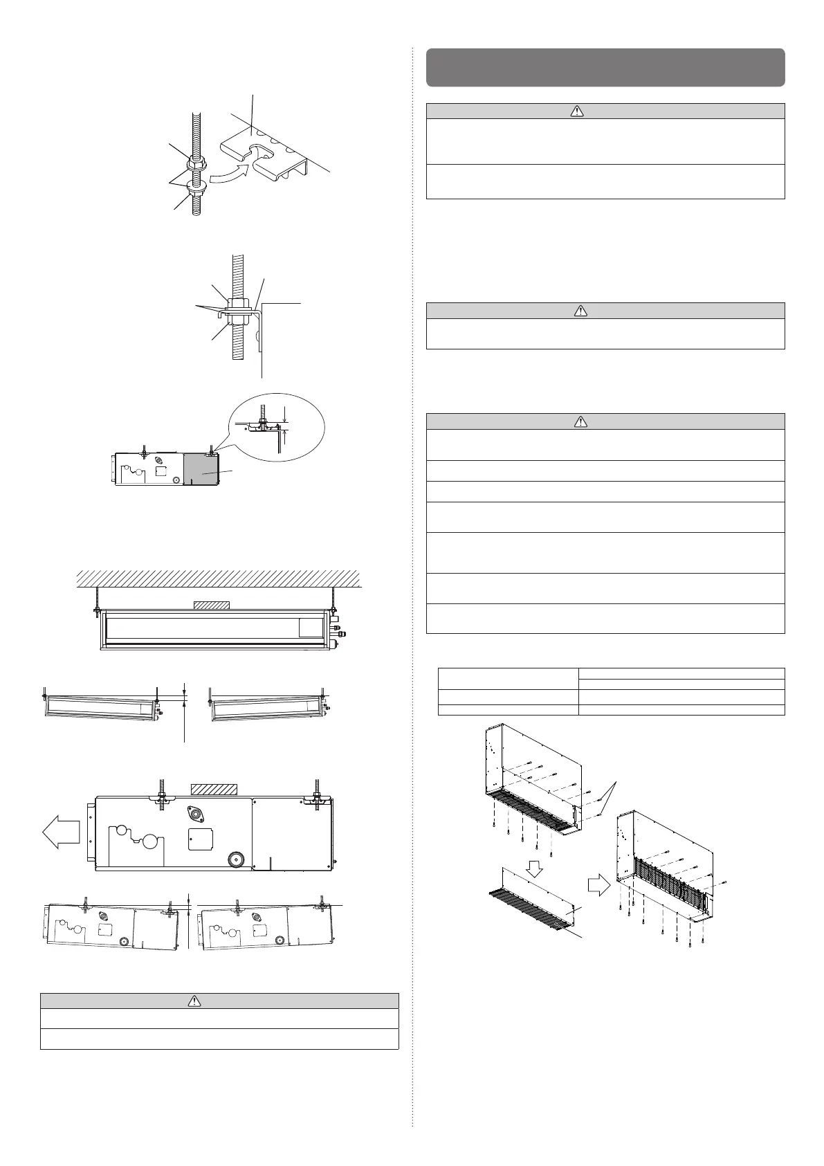
• Removethescrews,andthenremovecoverandfanguard.
• Installthecoverwiththescrewsasshownintheillustrationbelow.
Model
Screw
M5
7000,9000,12000,14000BTU/h 9
18000BTU/h 11
Cover
Fan guard
screw(M5)
3.3A.4. FIX THE UNIT
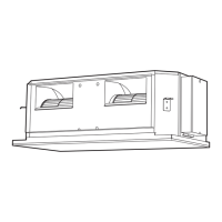
(1)Hangtheunit
Hangerbolt
Nut A
(Fieldsupply)
Nut B
(Fieldsupply)
Washer
(Accessories)
Hanger
Hangerbolt
Nut A
(Fieldsupply)
Washer
(Accessories)
Nut B
(Fieldsupply)
Unit
Hanger
20mm
length
Cover
*:It might become difficult to open and shut the Cover /control box cover when the
lengthexceeds20mm.
(2)Leveling
Base horizontal direction leveling on top of the unit.
Ceiling
Level
OK
NOGOOD
10mmorless
Level
Air
OK NOGOOD
10mmorless
CAUTION
• Leaveaspaceof100mmormorebetweentheinletportandtheceiling.
• FastentheunitsecurelywithSpecialnutsAandB.
9374815173-04_IM.indb 5 9/21/2011 1:45:17 PM
 Loading...