En-17
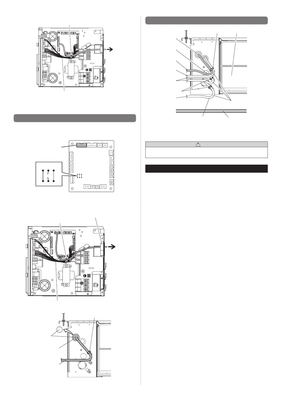
• Wiringarrangement
Binder(Medium/Accessories)
Bind with this cable.
• Use7pinsforreceiverunitcable.
•
Atrst,connectthereceiverunitcabletotheReceiverunitterminal(CN13).
]
1
9.5. Auto louver grille (Optional parts)
Connection method
• Connectionterminalandjumperwires
Auto louver grille
terminal(CN11)
Jumperwires
• CutJumperwireJM2
• Wiringarrangement
Binder(Medium/Accessories)
Bushing(Accessoryofoptionalparts)
Bind with this cable.
Auto louver grille cable
Bushing(Accessory
ofoptionalparts)
Binder(Medium/Accessories)
Openingthis
knockout hole
]
1
9.6. Optional parts cable binding
Auto louver
grille cable
Remote controller
cable
Otheroptional
parts cables
Powersupply
cable
Avoid touching the
ceiling with the wiring.
*Useanaccessoryofindoorunitoroptionalpartsforbinder.
**Useanaccessoryofoptionalpartsforbushing.
Ceiling
Avoid covering the air
inlet with the wirings.
Binders*
Air inletBinder*
Knockout hole
Bushing**
• Donotbindthepowersupplycableandothercablestogether.
CAUTION
• To protect the cable insulation after opening a knockout hole, remove any burrs from
the edge of the hole.
10. CUSTOMER GUIDANCE
Explainthefollowingtothecustomerinaccordancewiththeoperatingmanual:
(1)Startingandstoppingmethod,operationswitching,temperatureadjustment,timer,air
owswitching,andotherremotecontrolleroperations.
(
2)Airlterremovalandcleaning,andhowtousetheairlouvers.
(3)Givetheoperatingandinstallationmanualstothecustomer.
(4)Ifthesignalcodeischanged,explaintothecustomerhowitchanged(thesystem
returnstosignalcodeAwhenthebatteriesintheremotecontrollerarereplaced).
*(4)isapplicabletousingwirelessremotecontroller.
9374815173-04_IM.indb 17 9/21/2011 1:45:28 PM
 Loading...