En-16
9. OPTIONAL PARTS
]
WARNING
•
Regulation of cable differs from each locality, refer in accordance with local rules.
This air conditioner can be connected with the following optional kits. Refer to each
installation manual for the method of installing optional parts.
• Wiredremotecontroller
• Simpleremotecontroller
• Externalconnectkit
• Remotesensorunit
• IRReceiverunit
• Autolouvergrille
9.1. Wired remote controller (Simple remote controller)
Pleasereferto[6.ELECTRICALWIRING]and[7.REMOTECONTROLLERSETTING].
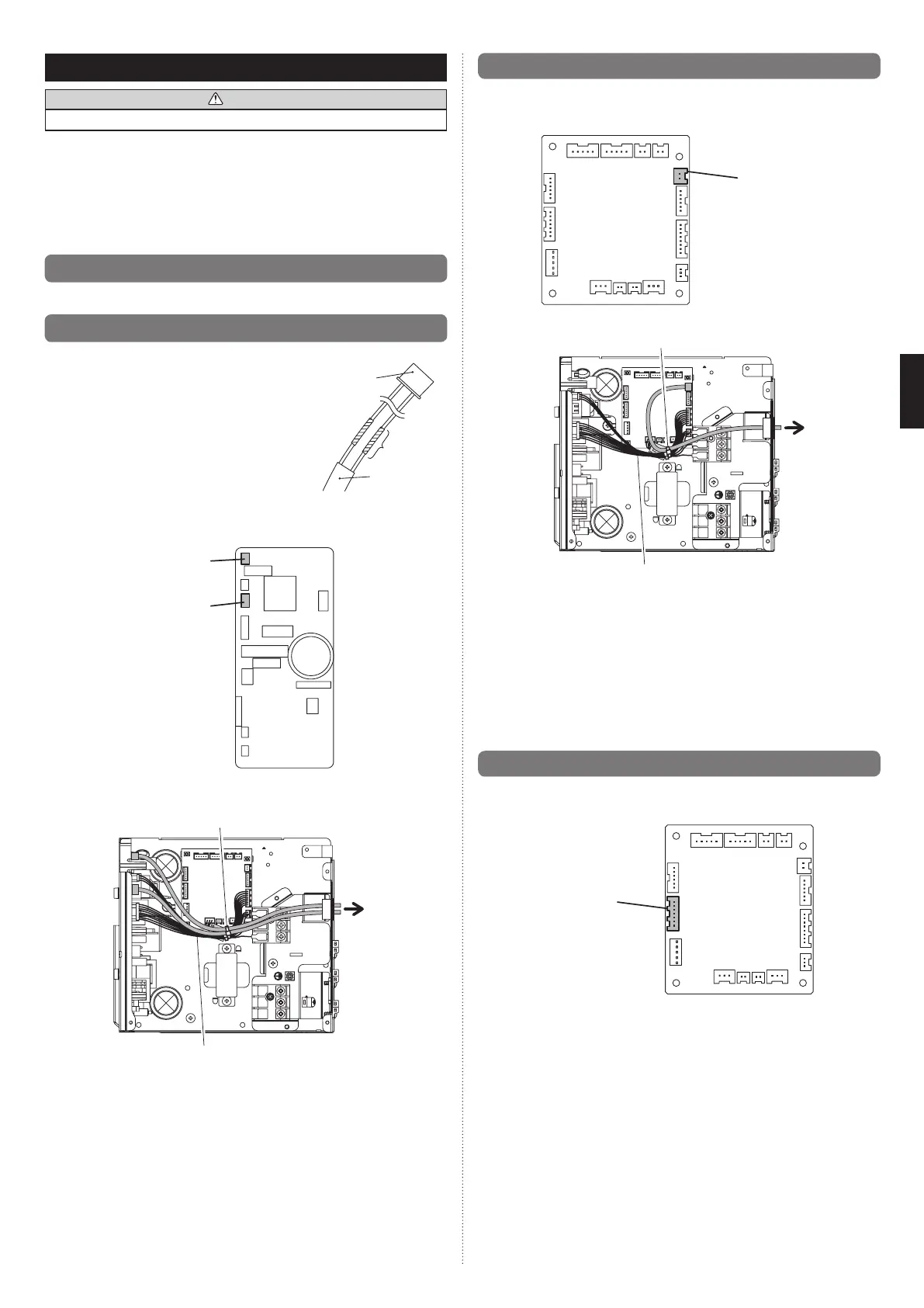
9.2. External input and external output
Connection methods
Wiremodication:
Useatooltocut offtheterminal onthe endof the
wire, and then remove the insulation from the cut
end of the wire.
Connectthewirewithconnectingwirewithsolder.
Important:
Be sure to insulate the connection between the
wires.
• Connectionterminals
Outputterminal(CN103)
InputNoVoltageterminal(CN102)
• Wiringarrangement
Binder(Medium/Accessories)
Bind with this cable.
]
1
9.3. Remote sensor (Optional parts)
Connection method
• Connectionterminals
Remote sensor
terminal(CN8)
• Wiringarrangement
Binder(Medium/Accessories)
Bind with this cable.
• Removetheexistingconnectorandreplaceitwiththeremotesensorconnector(ensure
thatthecorrectconnectorisused).
• Theoriginalconnectorshouldbeinsulatedtoensurethatitdoesnotcomeintocontact
with other electrical circuitry.
Settingforroomtemperaturecorrection
When a remote sensor is connected, set the function setting of indoor unit as indicated
below.
• SetFunctionNumber“30”(Coolingroomtemperaturecorrection)to“01”
• SetFunctionNumber“31”(Heatingroomtemperaturecorrection)to“01”
1
9.4. IR Receiver Unit (Optional parts)
Connection method
• Connectionterminals
Receiver unit
terminal(CN13)
Optionalparts
Externalinput/
output wire
Insulated
connection
Cable
(Fieldsupply)
9374815173-04_IM.indb 16 9/21/2011 1:45:28 PM
 Loading...