En-12
.
7. REMOTE CONTROLLER SETTING
CAUTION
When detecting the room temperature using the remote con-
troller, please set up the remote controller according to the
following conditions. If the remote controller is not located prop-
erly, the correct room temperature will not be detected, and
thusabnormalconditions like“not cooled”or“not heated”will
occur even if the air-conditioner is running normally.
• Locatewhereanaveragetemperaturefortheroombeing
air conditioned will be sensed.
• Donotlocatedirectlyexposedtotheoutletairfromthe
air-conditioner.
• Locateoutofdirectsunlight.
• Locateawayfromtheinuenceofotherheatsources.
DonottouchtheremotecontrollerPCboardandPCboardpartsdirectlywithyourhands
.
Do not wire the remote controller cable together with or parallel to the connection ca-
bles,andpowersupplycableofthe INDOORUNITandOUTDOORUNIT,BRANCH
BOX.Itmaycauseerroneousoperation.
When installing the bus wire near a source of electromagnetic waves, use shielded wire
.
DonotsettheDIPswitches,eitherontheairconditionerortheremotecontroller,inany
way other than indicated in this manual that is supplied with the air conditioner. Doing
so may result in improper operation.
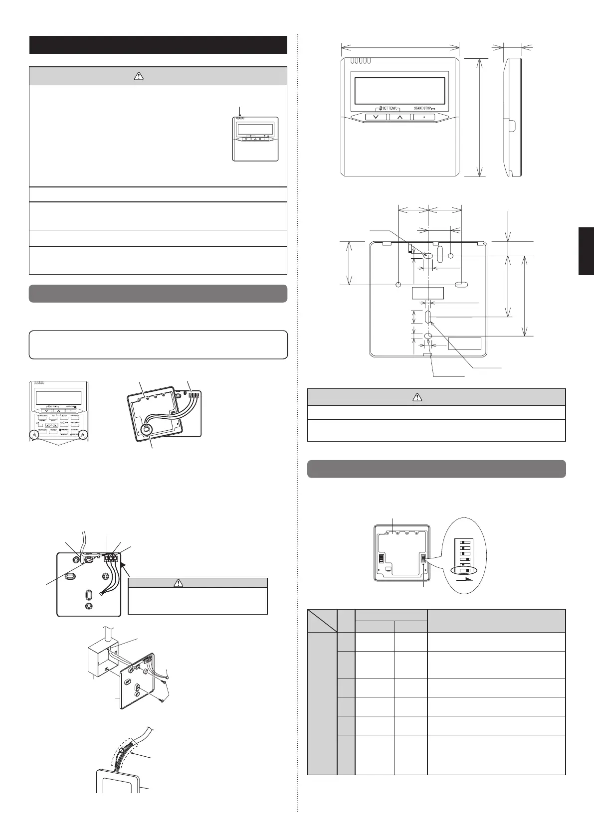
7.1. Installing the remote controller
Opentheoperationpanelonthefrontoftheremotecontroller,removethe2screwsindi-
catedinthefollowinggure,andthenremovethefrontcaseoftheremotecontroller.
When installing the remote controller, remove the connector from the front case. The
wires may break if the connector is not removed and the front case hangs down.
When installing the front case, connect the connector to the front case.
Screws
Front case
(backside)
Rear case
Connector
When remote controller cable is concealed
(1) Concealtheremotecontrollercable.
(2) Passtheremotecontrollercablethroughtheholeintherearcaseandconnectthe
remotecontrollercabletotheremotecontrollerterminalboardspeciedingure.
(3) Clamptheremotecontrollercablesheathwiththebinderasshowningure.
(4) Cutofftheexcessbinder.
(5) Installtherearcasetothewall,box,etc.,with2screwsgure.
Binder
(Small)
1.Red
2. White
3. Black
CAUTION
When connecting the remote controller
wires, do not overtighten the screws.
Hole
[Example]
Remote
controller cable
Box
Screws
Connector
Rear case
Groundtheremotecontrollerifithasagroundwire.
Wrap the connector and remote
controller wires with vinyl tape
or some other type of insulation
asshowninthegure.
Remote controller
30
120
17
120
45.3
33.5
Hole
15.3
23
8
4.5
4.5
4.5 12.5
Hole×3
Hole×2
83.5
63.5
6
Unit:mm
CAUTION
Install the remote controller wires so as not to be direct touched with your hand.
Donot touchthe remote controllerPC boardand PC boardparts directly withyour
hands.
7.2. Setting the dip switches
SettheremotecontrollerDIPswitches.
[Example]
DIPswitch1
Frontcase(backside)
NO.
SW state
Detail
OFF ON
DIP-
switch 1
1
★
Cannotbeused.
(Donotchange)
2
★
Dual remote controller setting
*Referto2.DUALREMOTECONTROL-
LERSin7.5.SpecialInstallationMethods.
3
★
Cannotbeused.
(Donotchange)
4
★
Cannotbeused.
(Donotchange)
5
★
Cannotbeused.
(Donotchange)
6
★
Invalidity Validity
Memorybackupsetting
*SettoON tousebatteries forthememory
backup. If batteries are not used, all of the
settings stored in memory will be deleted if
there is a power failure.
(
★
Factorysetting)
9374815173-04_IM.indb 12 9/21/2011 1:45:25 PM
 Loading...