En-4
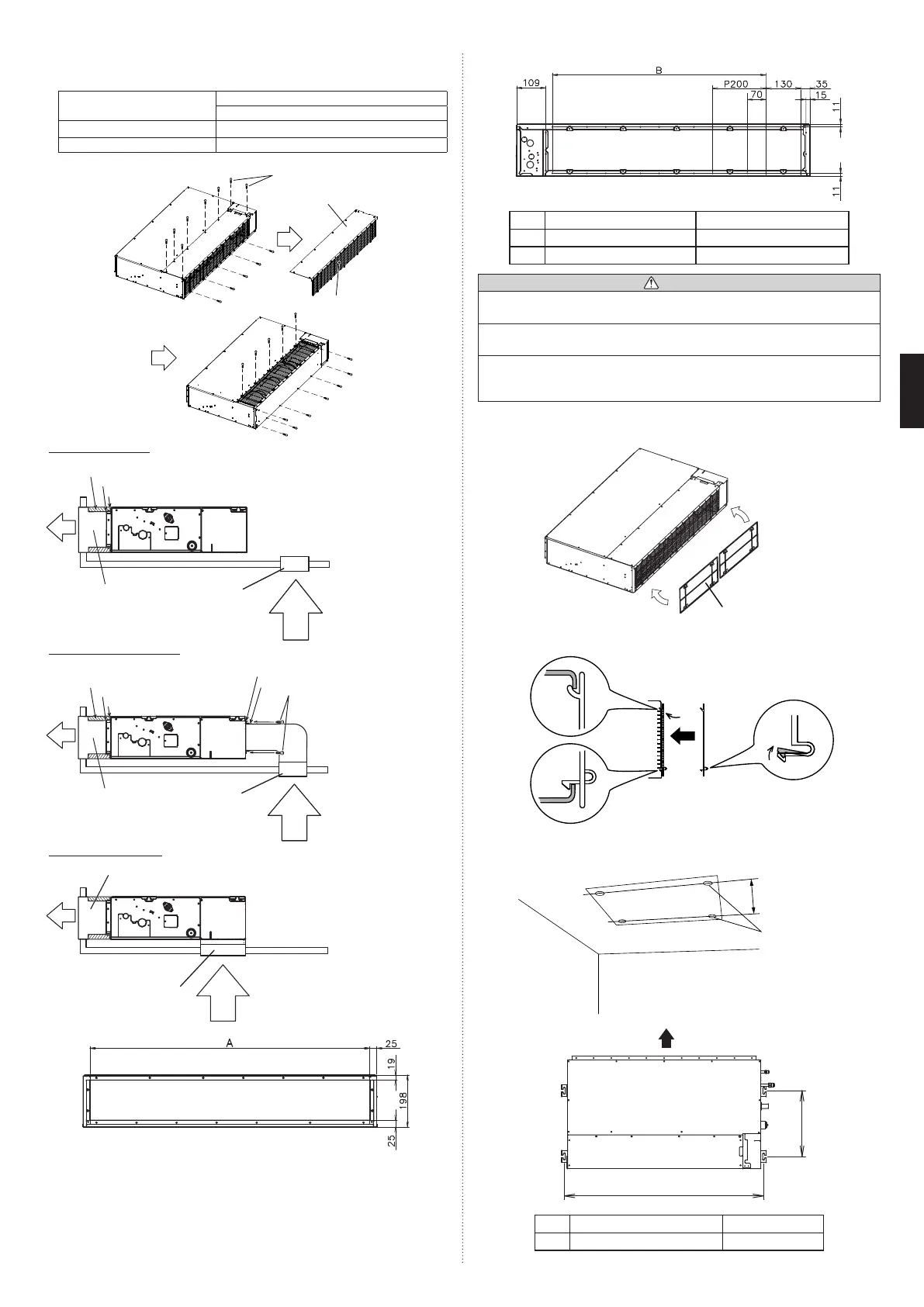
Replace the cover as follows.
• Removethescrews,andthenremovecoverandfanguard.
• Installthecoverwiththescrewsasshownintheillustrationbelow.
Model
Screw
M5
7000,9000,12000,14000BTU/h 9
18000BTU/h 11
screw(M5)
Cover
Fan guard
SideInlet-SideOutlet
Insulationmaterial(Fieldsupply)
Aluminum tape
Flange(Fieldsupply)
Air
Duct
(Fieldsupply)
Air
Intake grille
(Fieldsupply)
SideInlet-SideOutlet(Duct)
Insulationmaterial(Fieldsupply)
Aluminum tape
Aluminum tape
Tapping screw for
angeconnection
(M5x10mm/
Fieldsupply)
Flange(Fieldsupply)
Flange(Fieldsupply)
Air
Duct
(Fieldsupply)
Air
Intake grille
(Fieldsupply)
BottomInlet-SideOutlet
Duct(Fieldsupply)
Intakegrille(Fieldsupply)
Air
Air
Outletside
Inlet side
7000,9000,12000,14000BTU/h 18000BTU/h
A 650mm 850mm
B P200×2=400mm P200×3=600mm
CAUTION
• Be sure to install the air inlet grille and the air outlet grille for aircirculation. The
correct temperature cannot be detected.
• Grills mustbexed so that man cannot touch indoor unit fan and exchanger, and
cannot be removed by only hand operation without tool.
• Besuretoinstalltheairlterintheairinlet.
If the air fi lter is not installed, the heat exchanger may be clogged and its
performance may decrease.
3.3A.2. INSTALL THE FILTERS
• Installthelterstotheunit.
Filter(Accessories)
Unit
Filter
3.3A.3.
DRILLING HOLES FOR BOLTS AND INSTALLING THE BOLTS
• Usingtheinstallationtemplate,drillholesforbolts(4holes).
Drilling position
for bolts
Installation template
A
Air
377mm
7000,9000,12000,14000BTU/h 18000BTU/h
A 734mm 934mm
9374815173-04_IM.indb 4 9/21/2011 1:45:12 PM
 Loading...