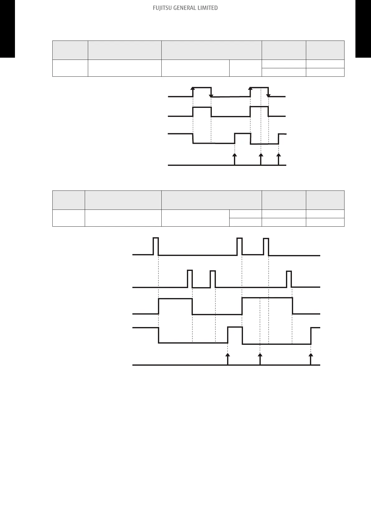
• When function setting is “Forced stop” mode
– In the case of “Edge” input:
Function
setting
Rotary SW on External
Input and Output PCB
External input Input signal Command
46-02 1
External Input and
Output PCB
CN313
Off → On Forced stop
On → Off Normal
On
Off
Forced stop
Normal
Operation
Stop
Remote controller
On On
Indoor unit
On
CN313
– In the case of “Pulse” input:
Function
setting
Rotary SW on External
Input and Output PCB
External input Input signal Command
46-02 1
External Input and
Output PCB
CN313 Pulse Forced stop
CN314 Pulse Normal
On
Off
Operation
Stop
Remote controller
On
Off
Forced stop
Normal
CN313
CN314
On On On
Indoorunit
NOTES:
• When the forced stop is triggered, indoor unit stops and Operation/Stop operation by the re-
mote controller is restricted.
• When forced stop function is used with forming a remote controller group, connect the same
equipment to each indoor unit within the group.
- 134 -
13-4. Details of function 13. External input and output (LPAS series wall mounted type indoor unit)
MULTI-SPLIT TYPE
5-unit type
MULTI-SPLIT TYPE
5-unit type
 Loading...