54 Operating Manual
TX2560 M2 / RX2560 M2
5.4 Connecting devices to the server
The connectors for external devices are on the front and rear of the server. The
additional connectors available on your server depend on the expansion cards
installed. For further information refer to the "FUJITSU Server PRIMERGY
TX2560 M2 / RX2560 M2 Server Upgrade and Maintenance Manual".
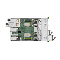
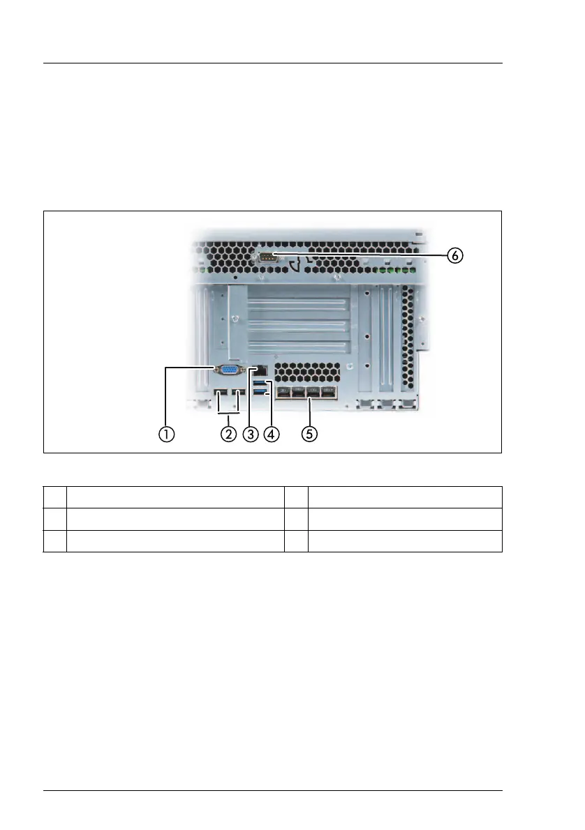
Figure 2: Connection panel on the rear
The corresponding indicators are explained in section "Rear of server" on
page 68.
I Some of the devices connected require special software (e.g. drivers)
(see documentation for the connected device).
I The LAN connectors on the dynamic LoM modules are numbered in
ascending order from right to left beginning with “0”. The rightmost
connector (LAN 0) is the shared LAN connector respectively.
Ê Connect the devices.
1 Video connector (blue) 4 USB 3.0 (blue)
2 USB 2.0 (black) 5 Dynamic LoM
3 Management LAN 6 Serial connector (optional)
 Loading...