J OIL-E-08 2008
TITLE FIG. NO.
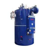
Oil Fired Steam Boiler 1
Boiler Top View 2
Typical Installation 3
Boiler Flue Connection 4
Boiler Feedwater Arrangements 5
Boiler Blowdown (20-60) 6
Boiler Blowdown (6-15) 6A
Water Column Sequencing Valve 7
Boiler Top Components 8
Steam Pressure Gauge 9
Nozzle and Ignition Assembly 10
Commissioning the Boiler 11
Pressure Controller 12
Operator Control Panels 13
Sequencing Blowdown Valve 14
Water Level Sight Gauge Blowdown 15
Fault Finding Check List 16
Maintenance 17
Handhole 18
Burner Assembly 19
Flue Cleaning 20
Boiler Dimensions 21
Boiler Supply Circuit 22
Ancillary Control Circuit 23
Spirax level Control Circuit 24
LC Level Control Circuit 25
TDS and Blowdown Control Circuit 26
6J - 30J Burner Control Circuit 27
40J - 60J Burner Control Circuit 28
SPARE PARTS
Boiler GA A0-2-1
Boiler Shell and Fittings 6-15 A1-1-1
Boiler Shell and Fittings A1-2-1
Burner Assembly 6-15 B2-1-1
Burner Assembly 20-30 B2-2-1
Burner Assembly 40-60 B2-3-2
Burner Scroll 6-15 D2-1-1
Burner Scroll 20-30 D2-2-1
Burner Scroll 40-60 D2-3-1
Burner Scroll, Dual Fuel, 40-60 D2-5-1
Water Column E1-6-1
Water Level Gauge Assembly (300mm) 6-60 F1-3-1
Water Level Gauge Assembly (350mm) 6-60 F1-4-1
Control Box Assembly, Dual Fuel, 40-60 G1-10-1
Control Box Assembly 6-15 G2-1-1
Control Box Assembly 20-30 G2-2-1
Control Box Assembly 40-60 G2-3-1
Feed Water Pump H1-1-1
LIST OF ILLUSTRATIONS
Optional Variations (wheretted) Appendix
Spirax High Integrity Level Controls C