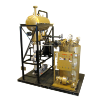
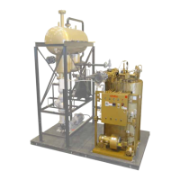
FT-C Vertical Electric Thermal Fluid Heater Manual 12 2013 ISSUE 1
Before ring the heater familiarise yourself on the use of the controls, lighting, and shutdown
procedures.
The burner is of forced design. The sequence of operation is as follows:
1) The ame programmer opens the main gas valve once stable pilot ame is established.
2) Pressure regulators on both the pilot and main gas supply, supply pressure to the proper level.
Note the maximum inlet pressure rating of each regulator and supply a step-down regulator if required.
3) Combustion air is delivered by a centrifugal blower fan. An air switch monitors the pressure and
is part of the ame programmer safety interlock circuit.
4) The ame programmer monitors the safe operation of the burner. Functions include pre-purge
of the combustion chamber, provision of ignition via the ignition transformer and electrode,
opening the pilot gas valve, monitoring the pilot ame signal via the ame sensor, opening main
gas valves and providing post-purge of the combustion chamber.
The ame is monitored by a ame sensor. In the event of insufcient, unstable, or non
existent pilot or main ame, the ame sensor will cause a safety lockout of the ame
programmer. Safety lockout can also be caused if the ame sensor is improperly positioned or
grounded. After fault has been corrected, reset by pressing the reset button on the casing of the
burner control box.
The sequence of operation for the on/off burner is as follows:
1) Beginning with power on, limit switch closed, fuel valves closed, and temperature controller
calling for heat, the ame programmer starts the cycle and the blower motor starts prepurge.
2) The air proving switch must be closed now. Air dampers remain in maximum position.
3) (Gas Pilot) Provided all safety interlocks are proven, ignition and pilot are energised and a
timed trial for pilot ignition begins. After the pilot ame is proven, the main fuel valve is
energised. Ignition is turned off when ame is registered and the main gas valves open.
4) (Spark Ignition) At the end of purge time, provided all safety interlocks are proven, the spark is
on and oil valves are opened. When the ame is proven, the spark is shut off.
5) When the uid temperature reaches the off setting (typically the setpoint plus 2 to 5 degrees) of
the operating temperature controller, all fuel valves are closed.
The burner motor stops and the entire system is ready for restart on demand.