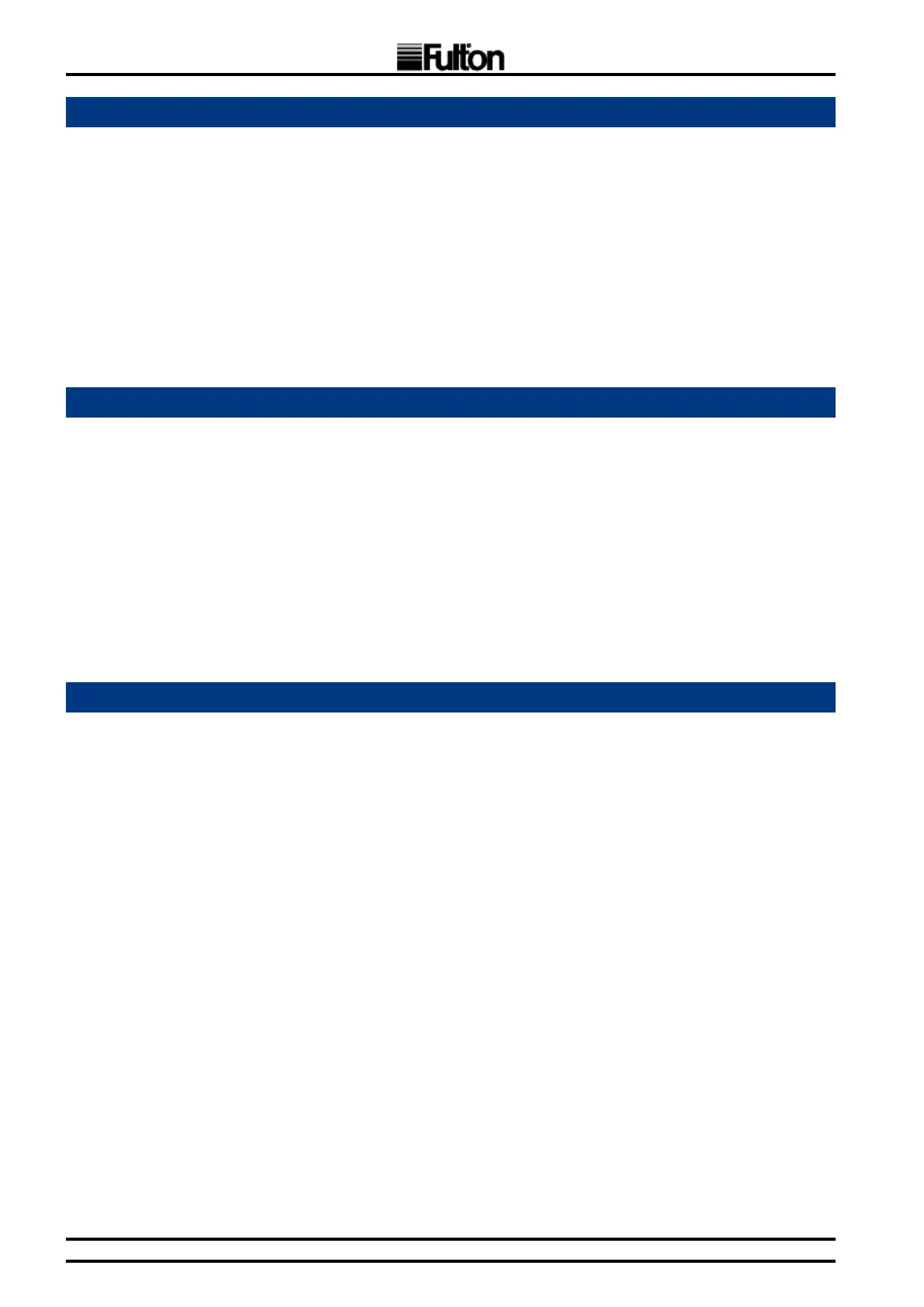
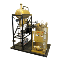
FT-C Vertical Electric Thermal Fluid Heater Manual 12 2013 ISSUE 1
Adhere to the following:
1. Locate the liquid level switch and install prior to operation of the equipment. The liquid level
switch is wired to the main heater panel. Failure to “make” this switch will result in lack of
power at the panel.
2. In the event of system uid loss, the level in the expansion section of the combination tank
will drop, and the liquid level switch will shut the unit down. Control power will be lost to the
panel.
3. To conrm operation, manually trip the liquid level switch. Unit should shut down; pump will
stop.
1. The air safety switch is installed in the heater panel and is connected by tubing to the blower
outlet. This switch requires that the blower fan deliver combustion air before energizing any fuel
valves.
2. While ring, disconnect the copper line from the tting in the top cover of the air switch. The
burner should shut down. Attempt to restart the unit by resetting the ame programmer.
3. Blower motor will start, but ring sequence should not begin.
4. Lockout of LMV will occur.
For units equipped with manual trip test button or motor starter.
1. While ring, actuate the manual trip button on blower motor starter. Unit should lock out.
Attempt re-start by resetting the ame programmer.
Purge cycle will not begin.
2. Reset motor starter; blower should start and purge cycle will begin.
3. Lockout of LMV will occur.