FT-C Vertical Electric Thermal Fluid Heater Manual 12 2013 ISSUE 1
20
23
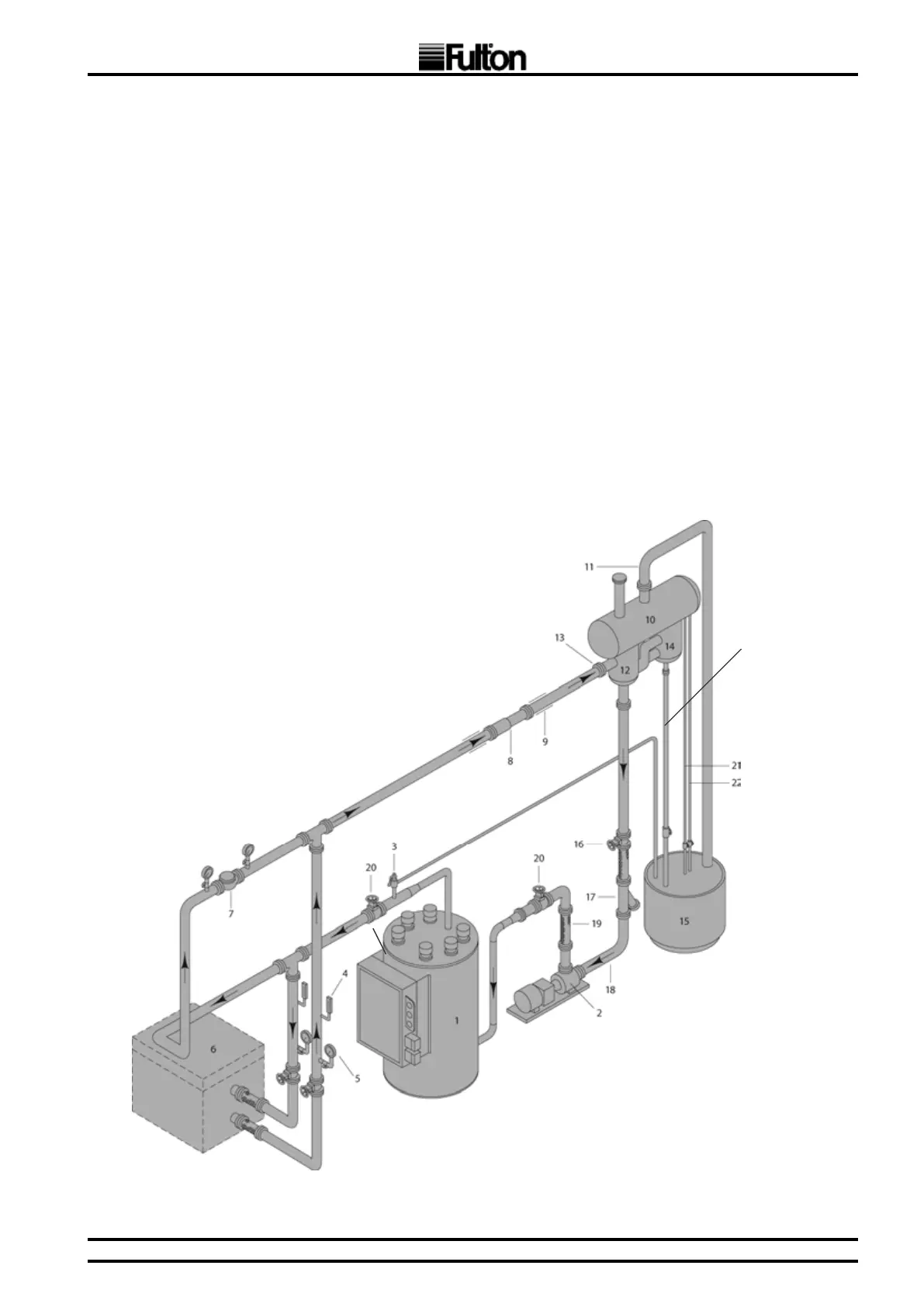
1. Thermal Fluid Heater
2. Thermal Fluid Circulating Pump
3. Safety Relief Valve
4. Thermometer
5. Pressure Gauge
6. Thermal Fluid Heated Equipment
7. Bypass Valve to maintain full flow to heater
8. Expansion Joints as required
9. Anchor and Pipe Guides as required
10. Expansion Tank
11. Vent Piping should be full size of expansion tank vent
12. Deaerator Tank
13. Deaerator Tank inlet must be highest point of piping
14. Thermal Buffer Tank
15. Catch Tank for drain of pressure relief valve, cold seal,
expansion tank, and vent. Locate in safe area.
16. Gate Valve
17. Strainer
18. ¾” System Fill Connection
19. Flexible Connection as necessary
20. Isolating Valve as necessary
21. Manual Low Level Test Line
22. Manual High Level Test Line
23. Buffer Drain
Full pump design flow must be maintained at all
times thru the main piping loop. Low flow will
seriously damage heater.
Note: Manifold configuration for illustration only.
See drawing appropriate to particular model.
j) Ensure that all bolts are tightened evenly and to the torque recommended values provided
by the gasket manufacturer.
k) High point bleeds are to be installed at all high points in the system piping. DN15 x 300 mm
nipples welded in the top of the piping with ball valves & plugs attached are to be used.
l) It will save a considerable amount of time during the cold ltration if the thermal system
piping is cleaned prior to assembly.
m) The mill scale (the results of oxidation) on the inside of the piping as well as construction
debris can foul the oil and cause the need for the lters to be cleaned more than need be.
This can range from simply using a rag to ordering pickled pipe. (“Pickling” is a process
where the piping is rst soaked in an acid bath, then soaked in a neutralizing bath, then
given a protective oil coating.)
n) All pipes should be installed with a pitch to facilitate draining and venting.
Inspect the system daily for leaking joints. Shut the system down and tighten any leaking anges or
connections immediately.
Full pump design ow must be maintained at all times
through the main piping loop. Low ow will seriously
damage the heater.