3 OPERATION
© Fulton 2018
3-4
VSRT_IOM_2018-1213
2. Once purge is completed, the control will drive
the blower speed, the air buttery and the gas
buttery to the ignition position.
3. Once all devices are stable, the control will
energize the ignition transformer, followed by
opening the pilot gas valve, igniting the pilot
ame.
4. Once pilot ame is established, the ignition spark
will de-energize, and the pilot ame must remain
proven by the scanner for a short safety time.
5. The main gas valve will now be energized,
supplying fuel to the burner, and lighting the
main ame.
6. The pilot valve turns o, and the main ame
must remain proven by the scanner for a second
short safety time.
7. The control now releases to modulation. The
ring rate will now be dictated by the load on the
system, as measured by the pressure controller.
8. The burner output will vary from high re down
to low re continuously in order to match load.
9. Once the system load has been satised (steam
pressure in the system exceed setpoint) the
burner will initiate it’s shutdown sequence.
10. If possible in time allotted (and if the system
is set-up and sized properly), the burner will
modulate to low re before shutting down.
Regardless of ring rate, the shutdown begins
with the main gas valve de-energizing, stopping
fuel ow to the burner.
11. The control will then drive air damper and the
blower to their specied post-purge position,
after which it will purge combustion gasses from
the unit for 15 seconds.
12. The control will then de-energize the blower
motor and drive all gas and air dampers to their
closed position
13. The burner will remain in the o state until the
system steam pressure falls below setpoint for
the burner to turn back on.
Flame Programmers
FLAME SAFEGUARD CONTROL
This is the main control in the panel box. The
programmer in conjunction with a sensing device
(UV scanner) supervises the ame ignition sequence,
proves that the ame is satisfactory and monitors the
established ame. Should any fault occur, either during
the ignition sequence or during normal operation, the
programmer will immediately go to “lock-out” and the
burner will shut down.
Siemens Linkageless Modulation
! WARNING
This information is for reference purposes only.
Fulton Companies is not responsible for this product,
including (but not limited to) its accuracy, reliability,
and safety. No Fulton document should substitute
for full review of documentation available from the
product manufacturer.
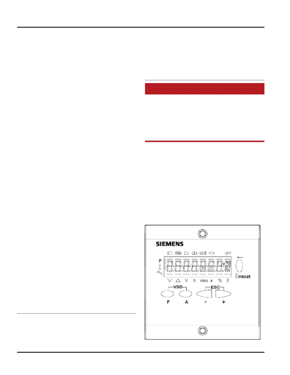
The Siemens LMV3 system is a fully packaged burner
management system, linkageless control and rst
out annunciator. When operating the Siemens LMV3
systems, all changes are made through the Siemens
AZL display. The left and right arrow keys are used for
scrolling through the menu and changing controller
parameters. “Enter” accepts the menu and parameter
changes. It is possible to return to the main menu at any
time by repeatedly pressing “Escape” (pressing the “+”
and “-“ keys at the same time). When running the boiler,
the status of the burner is to be monitored with the
Siemens AZL display (see below).