OPERATION 3
Questions? Call (315) 298-5121, or visit us online at www.fulton.com
3-7
VSRT_IOM_2018-1213
Operating Controls
The following specications, data, equipment and
operating descriptions apply to typical Vertical
Boiler units. These sections are provided for general
information purposes only, and do not necessarily
reect the specic details of individual systems.
At commissioning, the operation of all safeties and
interlocks should be veried. Setpoints of all pressure
and temperature switches as well as the programs for
all programmable controls (pressure controls, pressure
limits, operating controls, servo motors etc.) should
be recorded for future reference. Contact the Fulton
Service Department with any questions regarding the
proper operation, set points and verication procedures
for these controls.
Burner Settings
Burner combustion settings:
Typical O2 for proper combustion is 4.5-6%.
Typical O2 for the ignition position (P0) is 3.5-5%
for reliable light o and ame sensing..
» P0 set point is typically between P1 and P2
on combustion curve.
OTE: Pilot pressure range is to be 2.5” w.c.
to 3.5” w.c.
» Lower O settings can reduce burner mesh
life.
» Higher O settings will reduce the overall
eciency of the burner.
Boiler pressure controller is Yokogawa UT-32A.
Burner combustion adjustment guidelines:
Up Down
Fan Speed Adjustment More O, More Input Less O, Less Input
Gas Servo Adjustment More Input, Less O Less Input, More O
Air Servo Adjustment More O, Less Input Less O, More Input
SKP-25 Adjustment More Input, Less O Less Input, More O
Pressure Modulation Controller
ADJUSTMENT OF THE YOKOGAWA UT32A
OPERATING CONTROLLER:
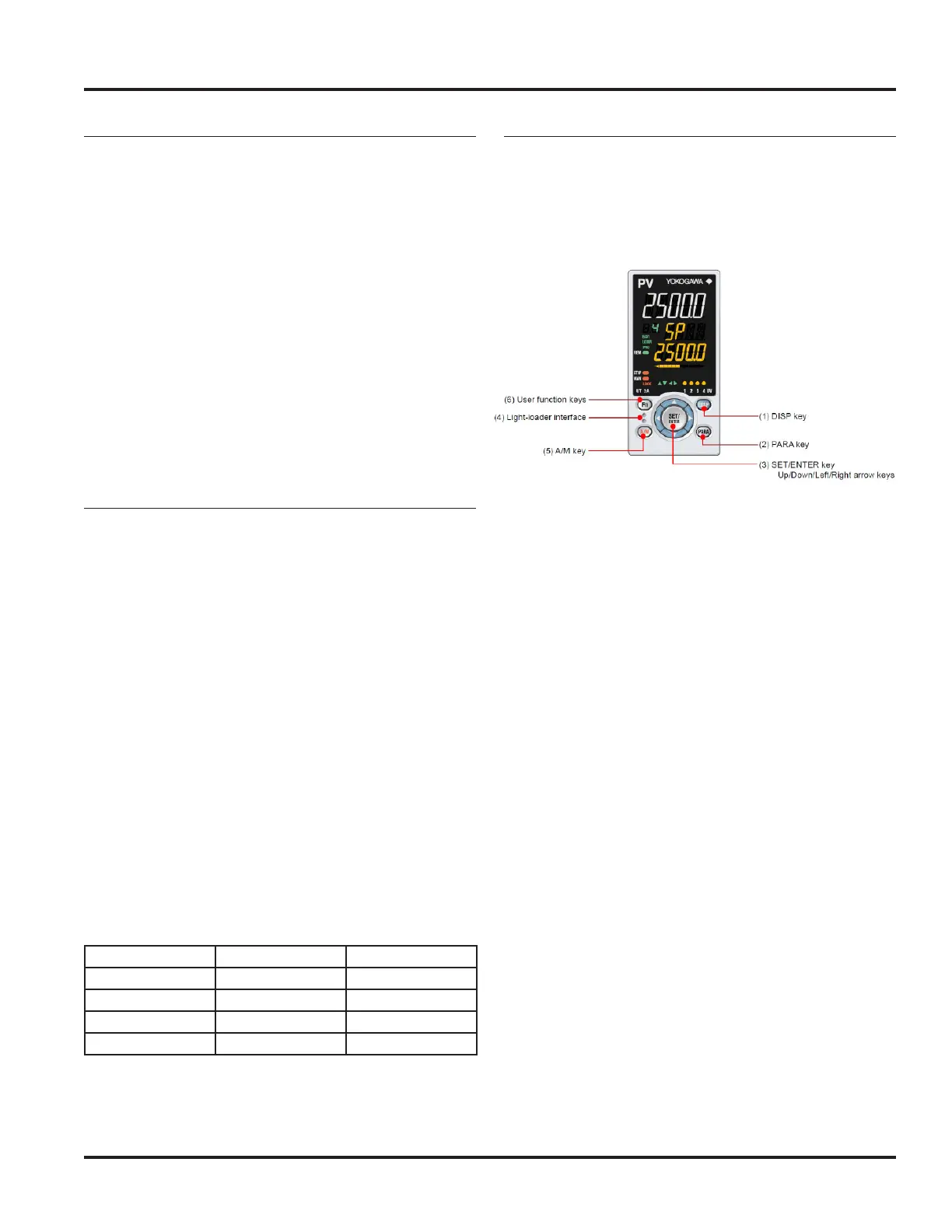
Front panel keys are shown below and explained in the
text that follows.
(1) – DISP key used to switch the Operation Displays.
Press the key in the Menu Display or Parameter
Setting Display to return to the Operation Display.
(2) – PARA key hold down the key for 3 seconds
to move to the Operation Parameter Setting
display. Hold down the key and the left arrow key
simultaneously for 3 seconds to move to the Setup
Parameter Setting Display. Press the DISP key in the
Parameter Setting Display to return to the Menu
Display. Press the SET/ENTER key once to cancel the
parameter setting (set point is blinking)
(3) SET/Enter key press the key in the Menu Display
to the Parameter Setting Display of the Menu. Press
the key in the Parameter Setting Mode to change
the set point.
(4) – Light-loader interface is the communication
interface to the adapter cable when setting and
storing parameters via PC.
(5) – A/M key used to switch between AUTO and
MAN modes.
(6) – Fn user function key dened by user. PID will
display when Fn key is pressed.
Parameter set-point adjustments are shown in the gure
on the next page and explained in the text that follows.