54
Master Insert and FX loop set-ups using outboard gear
Assuming you start with the relevant input channel gains, channel faders and master control settings
(and your power amplifiers muted) as in 1 to 5 above...
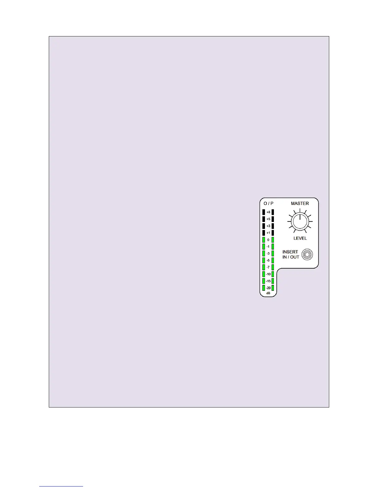
MASTER INSERT gain structure
a: Patch your effects unit into the FF-4000’s rear panel MAIN INSERT left and right jack sockets
(tip = send, ring = return) and switch it in circuit using the MASTER INSERT IN/ OUT button.
b: Set your outboard equipment’s input gain control so that its input signal indicators read
approximately -12dB below clip.
If your outboard gear only has signal present and clip input level indicators, adjust its input gain
control until the clip indicator just flashes and then back off the control by about 90° if
analogue – or by about 30% if digital.
c: If your outboard gear has separate output controls, set these for an output indication of
approximately -12dB below clip.
Again, if your outboard gear only has signal present and clip output level indicators, adjust its
output gain control until the clip indicator just flashes and then back off the control by about 90°
if analogue – or by about 30% if digital.
d: Now turn the FF-4000’s MASTER LEVEL control all the way down
(fully counter clockwise) and unmute your power amplifiers.
e: Slowly increase the MASTER LEVEL and listen to the inserted effect.
If the outboard gear is too noisy or has poor quality converters, you
may have to compromise on headroom by increasing the outboard
equipment’s input gain by a few dB and decreasing its output gain by
the same amount. A little experimentation may be required.
If the outboard gear is starting to sound distorted at your likely
maximum effect, you may need to reduce its input and/or output gain
slightly. Again, a little experimentation may be required.
A and B FX LOOP gain structure
X-Fade A/ FX Loop 1 is used as the example. The procedure for the X-Fade B/ FX Loop 2 is the same - with
the appropriate routing and selection changes, of course.
Again, assuming you start with the same input level signal - plus the relevant input channel gains,
channel faders and master control settings - and your power amplifiers muted, as in 1 to 5 above...
a: Patch your effects unit into the FF-4000’s rear panel FX LOOP 1 left and right jack sockets
(tip = send, ring = return) and switch it in circuit using the X-Fade A Latch ON button
(Make sure the LOOP SWAP button is not pressed – FX Loop 1 should follow A
– and make sure the X-Fade control has not been switched off)
b: Press the input channel strip X-FADE A and set the A-B cross-fader to A
www.funktion-one.com © Funktion One Research Limited 2011