4
1.4 GPS Antenna
Install the GPS antenna unit referring to the drawing on page D-5 or D-6 at the back
of this manual. When selecting a mounting location for the antenna, keep in mind the
following points.
• Select a location out of the radar beam. The radar beam will obstruct or prevent
reception of the GPS satellite signal.
• There should be no interfering object within the line-of-sight to the satellites.
Objects within line-of-sight to a satellite, for example, a mast, may block recep-
tion or prolong acquisition time.
• Mount the antenna unit as high as possible to keep it free of interfering objects
and water spray, which can interrupt reception of GPS satellite signal if the water
freezes.
Extending antenna cable
Three types of antenna cable extensions are optionally available.
a) Antenna cable set CP20-02700
• Waterproofing connector
Wrap connector with vulcanizing tape and then vinyl tape. Bind the tape end with a
cable-tie.
Waterproofing connector
b) Antenna cable set CP20-02710 (8D-FB-CV, 50m)
Connect the cable the same as a) above.
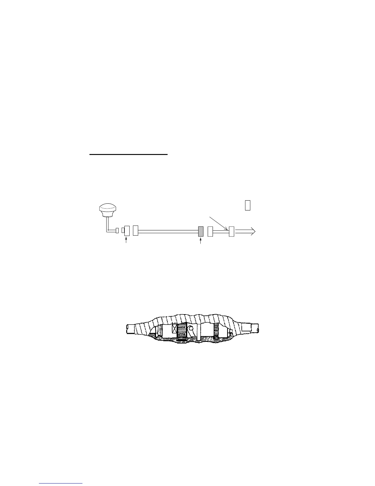
c) Cable type RG-10/UY (shipyard supply)
Note: The length of this cable should be less than 20 m to prevent signal loss. The
coax. coupling cable assy.(type: NJ-TP+3DXV-1, code no. 000-123-809), coaxial con-
nector(N-P-8DFB; supplied), vulcanizing tape and vinyl tape are required. Fabricate
both ends of the cable as shown in the figure on the next page.
Antenna Unit
Antenna Cable
30m 1 m
Fabricate locally. (See next page.)
N-P-8DFB
FA-50
: Connector
Conversion
Cable Assy.
NJ-JP-3DXV-1
TNCP-NJ
0.6m