1. INSTALLATION
1-9
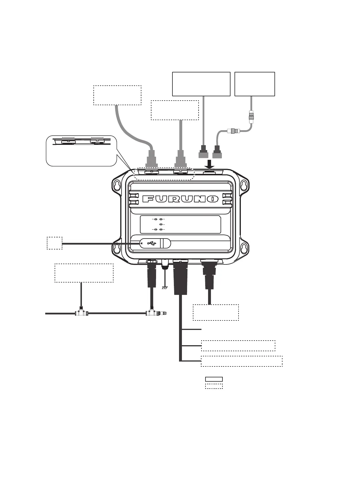
1.8 Wiring
Connect the equipment, referring to the figure below and the interconnection diagram
at the back of this manual.
Note 1: The FA-70 does not have a power switch. Install an external device (power
switchboard, etc.) from which to control its power.
Note 2: Connect the VHF antenna to the “VHF ANT” port, and the VHF radiotelephone
to the “VHF RADIO” port. If the VHF radiotelephone is connected to the “VHF ANT”
port, the VHF radiotelephone and the FA-70 may be damaged.
VHF Antenna
CX4-3/FEC
: Standard supply
: Optional or local supply
Option*: 8D-FB-CV,
30/40/50 m
Local supply*:
RG-10/UY, 20 m
or
TNC-PS/PS-3D-
L15M-R, 15 m
VHF
Radiotelephone
5D-2V
5D-2V
Ground
IV-1.25sq
NPD-MM1MF
1000G02M, 2 m
T-connector
NMEA2000 Sensor**
or External Display
NAV Equipment
or Sensor
MJ-A6SPF0003, Max. 15 m
*: NJ-TP-3DXV
(1 m) is required.
Ship’s Mains 12-24 VDC
NAV Equipment or Sensor
Contact Switch (Silent Switch)
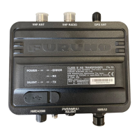
POWER
SILENT
ERROR
RX
TX
PC
**: GP-1871F/1971F, TZT9/14/BB, TZTL12F/15F,
TZT2BB, TZT12F/16F/19F, FAR-1416/1426,
FI-70, etc.
VHF ANT
port
VHF RADIO
port
Antenna Unit
GPA-017S
or
Antenna Unit
GPA-C01
or optional GPA-017
TNC-P-3,
10 m
VHF ANT VHF RADIO GPS ANT
NMEA2000
PWR/N-
MEA1/SI-
NMEA2
VHF ANT VHF RADIO
USB Cable, Max 2 m
To connect a monitor that supports NMEA2000
format version 1, set [NMEA2000] - [Format] to
[NMEA2000 V1] (see section 3.1). To connect
multiple monitors where one supports version 1
and the other supports version 2, connect one
of the monitors to the NMEA0183 port.
(Local supply)
(Option)