iv
TABLE OF CONTENTS
FOREWORD ....................................................................................................................v
SYSTEM CONFIGURATION .........................................................................................vii
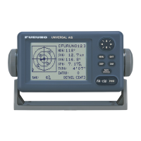
1. INSTALLATION .....................................................................................................1-1
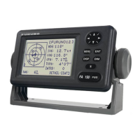
1.1 Equipment List ...........................................................................................................1-1
1.2 Included Items and Local Supplies ............................................................................ 1-4
1.3 Required Tools and Materials ....................................................................................1-5
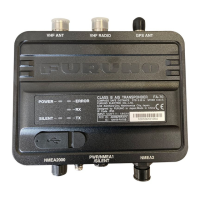
1.4 AIS Transponder FA-70 ............................................................................................. 1-5
1.5 GPS Antenna .............................................................................................................1-6
1.6 VHF Antenna (option) ................................................................................................1-7
1.7 AC-DC Power Supply (option) ...................................................................................1-8
1.8 Wiring.........................................................................................................................1-9
2. SHIP INFORMATION INPUT .................................................................................2-1
2.1 How to Install the Driver .............................................................................................2-1
2.2 How to Install the AIS Setting Tool............................................................................. 2-2
2.3 How to Start and Quit the AIS Setting Tool................................................................ 2-3
2.4 Overview of the AIS Setting Tool ............................................................................... 2-4
2.5 Initial Setup ................................................................................................................2-5
3. SETTINGS AND STATUS......................................................................................3-1
3.1 IO setup (input/output port) ........................................................................................ 3-1
3.2 Own Vessel Data Screen ...........................................................................................3-2
3.3 Alert Status.................................................................................................................3-3
3.4 IO Monitor ..................................................................................................................3-4
4. MAINTENANCE .....................................................................................................4-1
4.1 Maintenance...............................................................................................................4-1
4.2 Replacement of Fuse.................................................................................................4-1
4.3 Troubleshooting ......................................................................................................... 4-2
4.4 Diagnostics.................................................................................................................4-3
APPENDIX 1 MENU TREE .......................................................................................AP-1
APPENDIX 2 ALERT LISTS .....................................................................................AP-4
APPENDIX 3 NMEA2000/0183 INPUT/OUTPUT DATA ..........................................AP-5
APPENDIX 4 RADIO REGULATORY INFORMATION ............................................AP-7
SPECIFICATIONS .....................................................................................................SP-1
PACKING LIST ............................................................................................................ A-1
OUTLINE DRAWINGS................................................................................................. D-1
INTERCONNECTION DIAGRAM ................................................................................ S-1