11.1 Communication unit: FB-2000
11-14
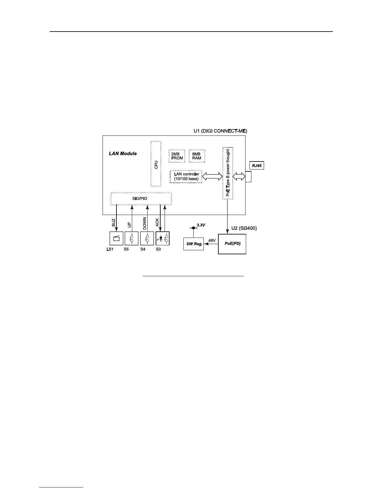
11.1.7 Incoming Indicator: FB-3000
Incoming indicator FB-3000 consists of a LAN Module and the PoE controller. The PoE
(Powered Device) specifications for the Incoming indicator are those conforming to
Type-B, Class-1. As for PoE, refer to page AP4-5.
The communication interface with the Communication unit (HUB) is 100Base-Tx.
U2 (Si3400) has a PD (Powered Device: on the PoE receiving terminal) interface and the
switching power supply functions.
Fig. 11.1.11 FB-3000 block diagram
Turn on the power for the Incoming indicator
When you connect the LAN cable;
1) Power of 2.7 - 11 V will be supplied from the Communication unit, and the HUB
acknowledges that the Incoming indicator has been connected based on the
detection resistance of the Incoming indicator.
2) Then the power of approx. 11 - 14 V is supplied, and the HUB acknowledges the
PoE Class based on the detection resistance of the Incoming indicator. FB-3000 is
Class-1.
3) Once the HUB acknowledges the class of the Incoming indicator, the HUB
supplies the voltage of 48 V.
4) The switching power will be activated, and the power of the Incoming indicator
will be turned on.
** As for Handset power on sequence, also same procedure used **