2 6 Thermocouple Input Wiring2 6 Thermocouple Input Wiring
Figure 2.5
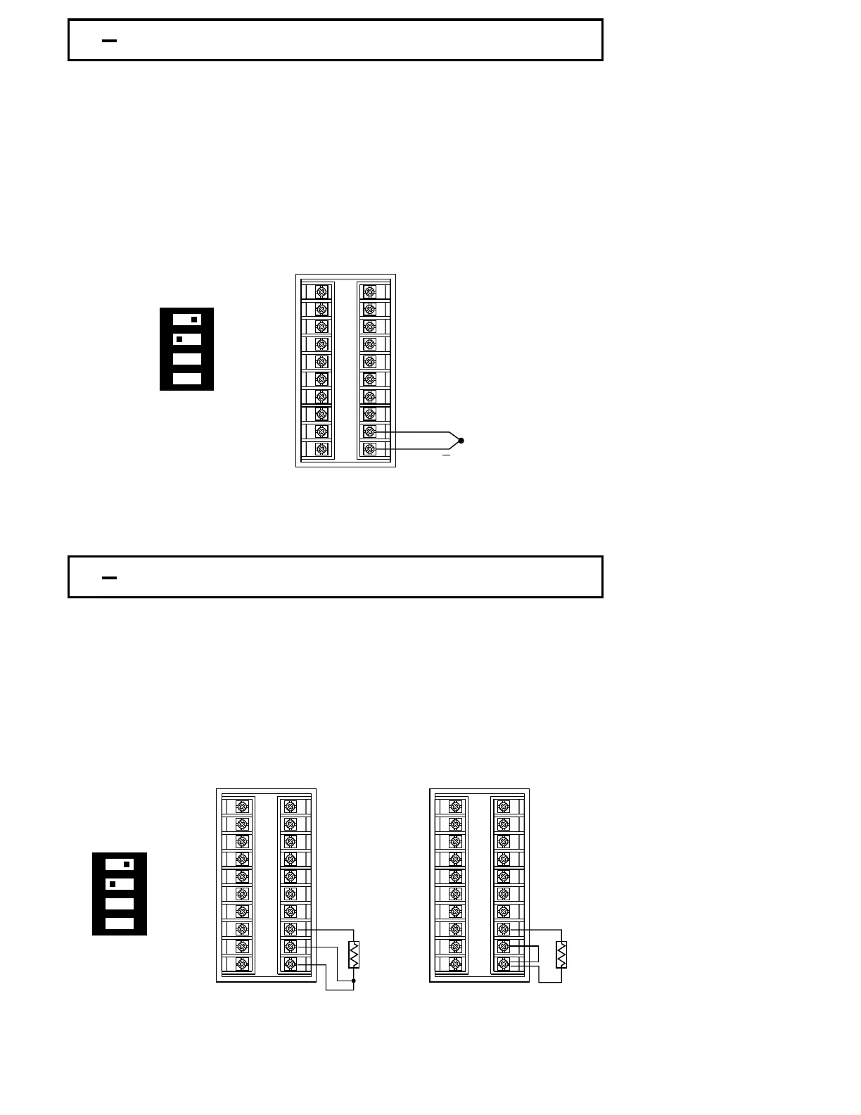
Thermocouple Input Wiring
Figure 2.5
Thermocouple Input Wiring
If the length of thermocouple plus the extension wire is too long, it may affect the
temperature measurement. A 400 ohms K type or a 500 ohms J type thermocouple
lead resistance will produce 1 degree C temperature error approximately.
If the length of thermocouple plus the extension wire is too long, it may affect the
temperature measurement. A 400 ohms K type or a 500 ohms J type thermocouple
lead resistance will produce 1 degree C temperature error approximately.
Thermocouple input connections are shown in Figure 2.5. The correct type of
thermocouple extension lead-wire or compensating cable must be used for the entire
distance between the controller and the thermocouple, ensuring that the correct
polarity is observed throughout. Joints in the cable should be avoided, if possible.
2 7 RTD Input Wiring2 7 RTD Input Wiring
Figure 2.6
RTD Input Wiring
Figure 2.6
RTD Input Wiring
Two-wire RTD should be avoided, if possible, for the purpose of accuracy. A 0.4
ohm lead resistance of a two-wire RTD will produce 1 degree C temperature
error.
Two-wire RTD should be avoided, if possible, for the purpose of accuracy. A 0.4
ohm lead resistance of a two-wire RTD will produce 1 degree C temperature
error.
RTD connection are shown in Figure 2.6, with the compensating lead connected to
terminal 12. For two-wire RTD inputs, terminals 12 and 13 should be linked. The
three-wire RTD offers the capability of lead resistance compensation provided that the
three leads should be of same gauge and equal length.
UM83001A-August-2024
18
+
1 2 3 4
ON
DIP SwitchDIP Switch
1
2
3
4
5
6
7
8
9
10
11
12
13
14
15
16
17
18
19
20
1 2 3 4
ON
DIP SwitchDIP Switch
Three-wire RTDThree-wire RTD Two-wire RTDTwo-wire RTD
RTD
1
2
3
4
5
6
7
8
9
10
11
12
13
14
15
16
17
18
19
20
RTD
1
2
3
4
5
6
7
8
9
10
11
12
13
14
15
16
17
18
19
20