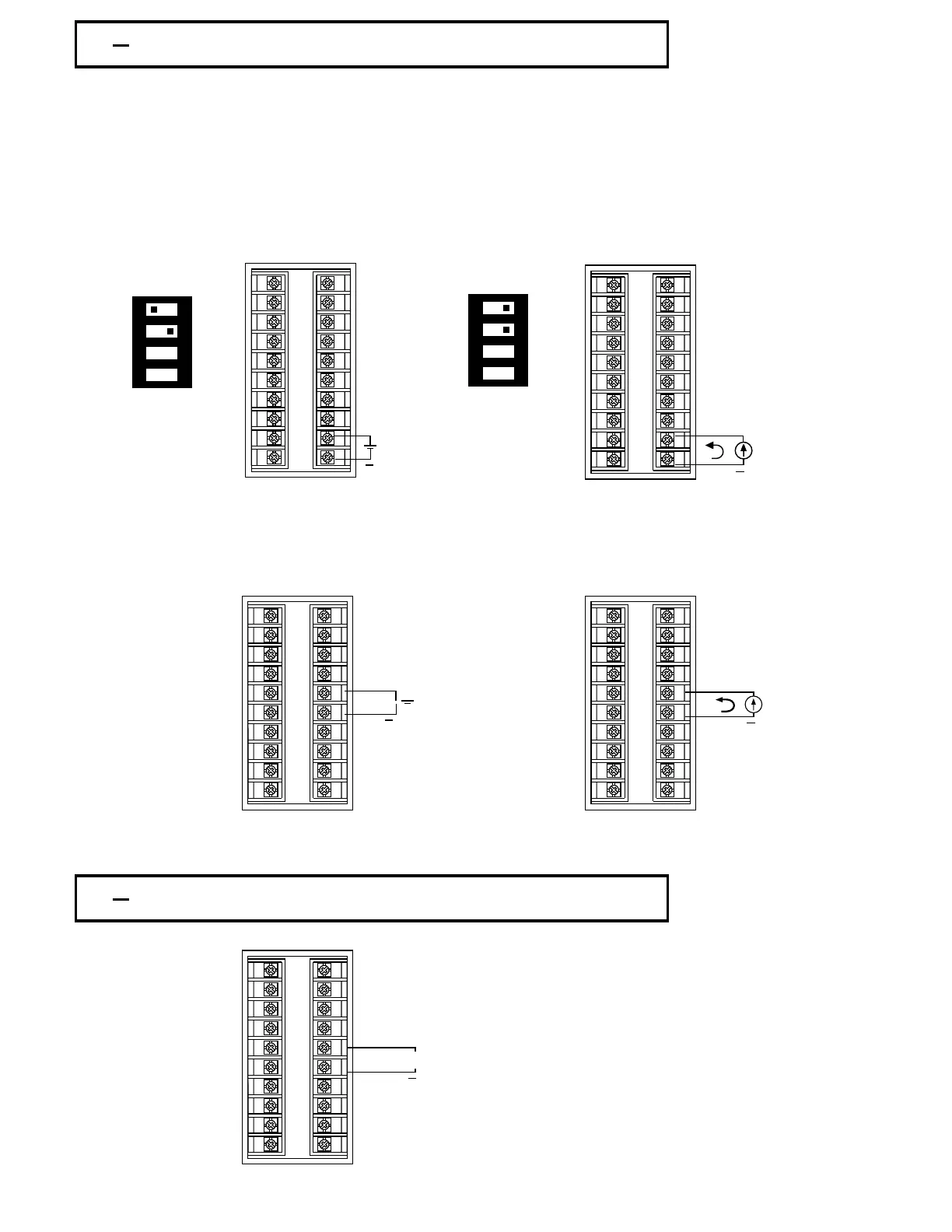
2 8 Linear DC Input Wiring2 8 Linear DC Input Wiring
DC linear voltage and linear current connections for input 1 are shown in Figure
2.7 and Figure 2.8 .
DC linear voltage and linear current connections for input 1 are shown in Figure
2.7 and Figure 2.8 .
DC linear voltage and linear current connections for input 2 are shown in Figure
2.9
and
Figure 2.10 .
DC linear voltage and linear current connections for input 2 are shown in Figure
2.9 and Figure 2.10 .
Figure 2.7
Input 1 Linear Voltage Wiring
Figure 2.7
Input 1 Linear Voltage Wiring
Figure 2.8
Input 1
Linear Current Wiring
Figure 2.8
Input 1 Linear Current Wiring
Figure 2.9
Input 2
Linear Voltage Wiring
Figure 2.9
Input 2 Linear Voltage Wiring
Figure 2.10
Input
2
Linear Current Wiring
Figure 2.10
Input 2 Linear Current Wiring
Figure 2.11
CT Input
Wiring for
Single Phase Heater
Figure 2.11
CT Input Wiring for
Single Phase Heater
2 9 CT / Heater Current Input Wiring2 9 CT / Heater Current Input Wiring
CT Signal Input *Total current CT94-1 not toCT Signal Input *Total current CT94-1 not to
exceed 50 A RMS.exceed 50 A RMS.
UM83001A-August-2024
19
0~1V, 0~5V
1~5V, 0~10V
0~1V, 0~5V
1~5V, 0~10V
+
0~20mA or
4~20mA
0~20mA or
4~20mA
+
+
1 2 3 4
ON
DIP SwitchDIP Switch
0~1V, 0~5V
1~5V, 0~10V
0~1V, 0~5V
1~5V, 0~10V
+
1
2
3
4
5
6
7
8
9
10
11
12
13
14
15
16
17
18
19
20
0~20mA or
4~20mA
0~20mA or
4~20mA
1 2 3 4
ON
+
1
2
3
4
5
6
7
8
9
10
11
12
13
14
15
16
17
18
19
20
DIP SwitchDIP Switch
1
2
3
4
5
6
7
8
9
10
11
12
13
14
15
16
17
18
19
20
1
2
3
4
5
6
7
8
9
10
11
12
13
14
15
16
17
18
19
20
1
2
3
4
5
6
7
8
9
10
11
12
13
14
15
16
17
18
19
20