2 12 Event Input wiring2 12 Event Input wiring
Figure 2.14
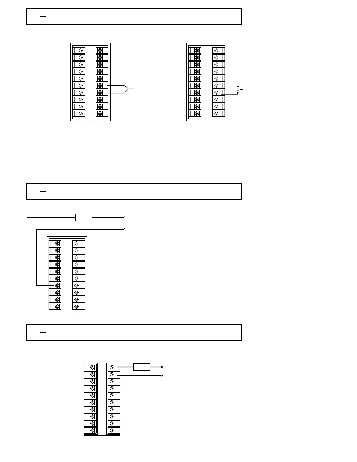
Event Input Wiring
Figure 2.14
Event Input Wiring
The event input can accept a switch signal as well as an open collector signal. The
event input function ( EIFN ) is activated as the switch is closed or an open collector
( or a logic signal ) is pulled down.
The event input can accept a switch signal as well as an open collector signal. The
event input function ( EIFN ) is activated as the switch is closed or an open collector
( or a logic signal ) is pulled down.
2 13 Alarm 1 Wiring2 13 Alarm 1 Wiring
Figure 2.15
Alarm 1 Wiring
Figure 2.15
Alarm 1 Wiring
2 14 Alarm 2 Wiring2 14 Alarm 2 Wiring
Figure 2.16
Alarm 2 Wiring
Figure 2.16
Alarm 2 Wiring
UM83001A-August-2024
22
Open Collector
Input
Open Collector
Input
Switch InputSwitch Input
+
120V/240V
Mains Supply
120V/240V
Mains Supply
Max. 2A resistiveMax. 2A resistive
Load
Relay Output
Alarm 1
Relay Output
Alarm 1
NOTE: Alarm 1 is a Form C Relay
Terminal
7 - Com
Terminal 8 - N.O.
Terminal 9 - N.C.
Example shows load wired across
Com and N.O. Contact
NOTE: Alarm 1 is a Form C Relay
T
erminal 7 - Com
Terminal 8
- N.O.
Terminal 9
- N.C.
Example shows load wired across
Com and N.O. Contact
120V/240V
Mains Supply
120V/240V
Mains Supply
Max. 2A
Resistive
Max. 2A
Resistive
Load
Relay OutputRelay Output
1
2
3
4
5
6
7
8
9
10
11
12
13
14
15
16
17
18
19
20
1
2
3
4
5
6
7
8
9
10
11
12
13
14
15
16
17
18
19
20
1
2
3
4
5
6
7
8
9
10
11
12
13
14
15
16
17
18
19
20
1
2
3
4
5
6
7
8
9
10
11
12
13
14
15
16
17
18
19
20