3 2 Dwell Timer3 2 Dwell Timer
SP1
PV
Time
ON
OFF
A1 or A2
Time
Time
TIME
Timer starts
Figure 3.1 Dwell Timer FunctionFigure 3.1 Dwell Timer Function
If alarm 1 is configured as dwell timer, A1SP, A1DV, A1HY and A1MD are hidden.
Same case is for alarm 2.
If alarm 1 is configured as dwell timer, A1SP, A1DV, A1HY and A1MD are hidden.
Same case is for alarm 2.
Set A1FN=TIMR or A2FN=TIMR but not both.
Adjust TIME
in minutes
A1MD ( if A1FN=TIMR ) or A2MD ( if A2FN=TIMR ) is ignored in this case.
If a form B relay is required for dwell timer, then order form B alarm 1 and
configure A1FN. Form B relay is not available for alarm 2.
Set A1FN=TIMR or A2FN=TIMR but not both.
Adjust TIME in minutes
A1MD ( if A1FN=TIMR ) or A2MD ( if A2FN=TIMR ) is ignored in this case.
If a form B relay is required for dwell timer, then order form B alarm 1 and
configure A1FN. Form B relay is not available for alarm 2.
Example :Example :
Error CodeError Code
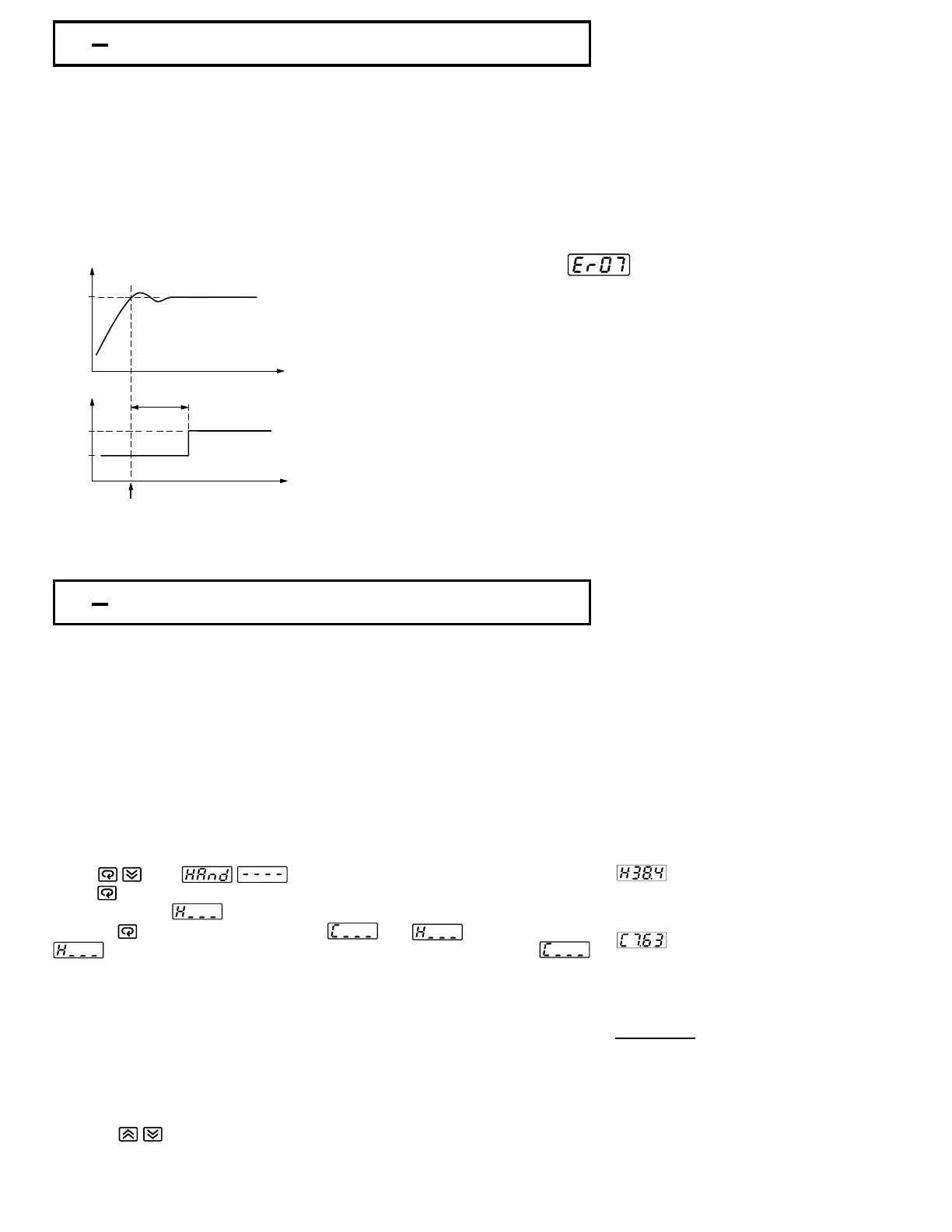
Alarm 1 or alarm 2 can be configured as dwell timer by selecting TIMR for
A1FN or
A2FN, but not both, otherwise will appear. As the dwell timer is
configured, the parameter TIME is used for dwell time adjustment.
The dwell time is measured in minute ranging from 0 to 6553.5 minutes. Once
the process reaches the set point the dwell timer starts to count from zero until
time out.The timer relay will remain unchanged until time out. The dwell timer
operation is shown as following diagram.
Er07
Alarm 1 or alarm 2 can be configured as dwell timer by selecting TIMR for
A1FN or A2FN, but not both, otherwise will appear. As the dwell timer is
configured, the parameter TIME is used for dwell time adjustment.
The dwell time is measured in minute ranging from 0 to 6553.5 minutes. Once
the process reaches the set point the dwell timer starts to count from zero until
time out.The timer relay will remain unchanged until time out. The dwell timer
operation is shown as following diagram.
Er07
3 3 Manual Control3 3 Manual Control
The manual control may be used for the following :purposesThe manual control may be used for the following :purposes
( 1 ) To test the process characteristics to obtain a step response as well as an
impulse response
and use these data for tuning a controller.
( 1 ) To test the process characteristics to obtain a step response as well as an
impulse response and use these data for tuning a controller.
(2)
NOTE
To use manual control instead of a close loop control as the sensor fails or
the controller's A-D converter fails. that a bumpless transfer can not
be used for a longer time. See section 3-6.
( 2 )
NOTE
To use manual control instead of a close loop control as the sensor fails or
the controller's A-D converter fails. that a bumpless transfer can not
be used for a longer time. See section 3-6.
( 3 ) In certain applications it is desirable to supply a process with a constant
demand.
( 3 ) In certain applications it is desirable to supply a process with a constant
demand.
Operation:
Press until ( Hand Control ) appears on the display.
Press for 3 seconds then the upper display will begin to flash and the lower
display will show . The controller now enters the manual control mode.
Pressing the lower display will show and alternately where
indicates output1(orheating ) control variable value MV1 and
indicates output2(orcooling ) control variable value MV2. Now you can use
up-down key to adjust the percentage values for H or C.
The controller performs open loop control as long as it stays in manual control
mode. The H value is exported to output 1 ( OUT1 ) and C value is exported to
output 2 provided that OUT2 is performing cooling function ( ie. OUT2 selects
COOL ).
Press until ( Hand Control ) appears on the display.
Press for 3 seconds then the upper display will begin to flash and the lower
display will show . The controller now enters the manual control mode.
Pressing the lower display will show and alternately where
indicates output 1 ( or heating ) control variable value MV1 and
indicates output 2 ( or cooling ) control variable value MV2. Now you can use
up-down key to adjust the percentage values for H or C.
The controller performs open loop control as long as it stays in manual control
mode. The H value is exported to output 1 ( OUT1 ) and C value is exported to
output 2 provided that OUT2 is performing cooling function ( ie. OUT2 selects
COOL ).
Exception
If OUT1 is configured as ON-OFF control
( ie. PB1=0 if PB1 is assigned or
PB2=0 if PB2 is assigned by event input ),
the controller will never perform
manual control mode.
If OUT1 is configured as ON-OFF control
( ie. PB1=0 if PB1 is assigned or
PB2=0 if PB2 is assigned by event input ),
the controller will never perform
manual control mode.
Exit Manual ControlExit Manual Control
To press keys the controller will revert to its previous operating mode
( may be a failure mode or normal control mode ).
To press keys the controller will revert to its previous operating mode
( may be a failure mode or normal control mode ).
Means
MV1=38.4 %
for OUT1 ( or Heating )
MV1=38.4 %
for OUT1 ( or Heating )
Means
MV2=7.63 %
for OUT2 ( or Cooling )
MV2=7.63 %
for OUT2 ( or Cooling )
UM83001A-August-2024
26