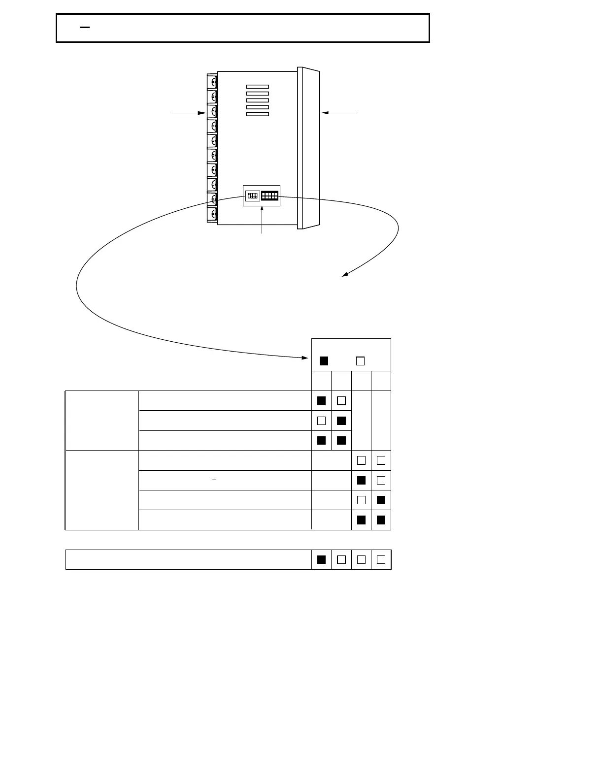
Front
Panel
Rear
Terminal
1 3 Mini Jumper and DIP Switch1 3 Mini Jumper and DIP Switch
Figure 1.2 Access Hole
Overview
Figure 1.2 Access Hole
Overview
Table 1.1 DIP Switch
Configuration
Table 1.1 DIP Switch
Configuration
UMA83001A-August-2024
TC, RTD, mV
0-1V, 0-5V, 1-5V, 0-10V
0-20 mA, 4-20 mA
Input 1
Select
Input 1
Select
All parameters are Unlocked
Only SP1, SEL1 SEL5 are unlocked
Only SP1 is unlocked
All Parameters are locked
Lockout
12
34
DIP SwitchDIP Switch
:ON :OFF
Factory Default SettingFactory Default Setting
*
*
The mini jumper ( programming port ) is used for off-line automatic setup and testing
procedures only. Don't attempt to make any connection to these jumpers when the
unit is used for a normal control purpose.
The mini jumper ( programming port ) is used for off-line automatic setup and testing
procedures only. Don't attempt to make any connection to these jumpers when the
unit is used for a normal control purpose.
When the unit leaves the factory, the DIP switch is set so that TC & RTD are selected for input
1 and all parameters are unlocked.
When the unit leaves the factory, the DIP switch is set so that TC & RTD are selected for input
1 and all parameters are unlocked.
Lockout function is used to disable the adjustment of parameters as well as operation of
calibration mode.
However, the menu can still be viewed even under lockout condition.
Lockout function is used to disable the adjustment of parameters as well as operation of
calibration mode. However, the menu can still be viewed even under lockout condition.
SEL1- SEL5 represent those parameters which are selected by using SEL1, SEL2,...SEL5
parameters contained
in Setup menu. Parameters been selected are then allocated at the
beginning of the user menu.
SEL1- SEL5 represent those parameters which are selected by using SEL1, SEL2,...SEL5
parameters contained in Setup menu. Parameters been selected are then allocated at the
beginning of the user menu.
Access Hole
The programming port is used to connect to
P10A hand-held programmer for automatic
programming, also can be connected to ATE
system for automatic testing & calibration.
The programming port is used to connect to
P10A hand-held programmer for automatic
programming, also can be connected to ATE
system for automatic testing & calibration.
ON DIP
1234
5