2 15 RS-4852 15 RS-485
Figure 2.17
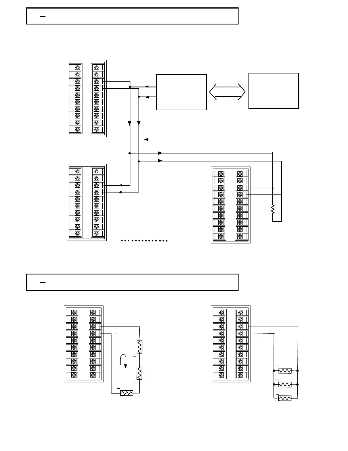
RS-485 Wiring
Figure 2.17
RS-485 Wiring
2 16 Analog Retransmission2 16 Analog Retransmission
0 - 20mA,
4 - 20mA
0 - 20mA,
4 - 20mA
Do not exceed 500 ohms total loadDo not exceed 500 ohms total load
Retransmit CurrentRetransmit Current
Minimum load must be greater than 10K ohms.Minimum load must be greater than 10K ohms.
Figure 2.18 Analog
Retransmission Wiring
Figure 2.18 Analog
Retransmission Wiring
Output typically used for Indicators PLC's Recorders Data loggers Inverters etc.Output typically used for Indicators PLC's Recorders Data loggers Inverters etc.
23
UM83001A-August-2024
TX1
TX1
TX2
TX2
Max. 247 units can be linkedMax. 247 units can be linked
TX1
TX2
RS-232
PC
SNA10A or
SNA10B
SNA10A or
SNA10B
Figure 2.18
RS-485 Wiring
Figure 2.18
RS-485 Wiring
RS-485 to RS-232
network adaptor
RS-485 to RS-232
network adaptor
Twisted-Pair WireTwisted-Pair Wire
TX1TX1
TX2TX2
Terminator
220 ohms / 0.5W
End unit of limk
Terminator
220 ohms / 0.5W
End unit of limk
+
+
+
Load
Load
Load
1-5V,0-5V
0 - 10V
1 - 5 V, 0 - 5V
0 - 10V
+
+
Retransmit VoltageRetransmit Voltage
Load
Load
Load
+
+
+
1
2
3
4
5
6
7
8
9
10
11
12
13
14
15
16
17
18
19
20
1
2
3
4
5
6
7
8
9
10
11
12
13
14
15
16
17
18
19
20
1
2
3
4
5
6
7
8
9
10
11
12
13
14
15
16
17
18
19
20
1
2
3
4
5
6
7
8
9
10
11
12
13
14
15
16
17
18
19
20
1
2
3
4
5
6
7
8
9
10
11
12
13
14
15
16
17
18
19
20