2 17 RS-2322 17 RS-232
TX1
TX2
COM
PC
9-pin
RS-232 port
9-pin
RS-232 port
Figure 2.19
RS-232 Wiring
Figure 2.19
RS-232 Wiring
CC94-1
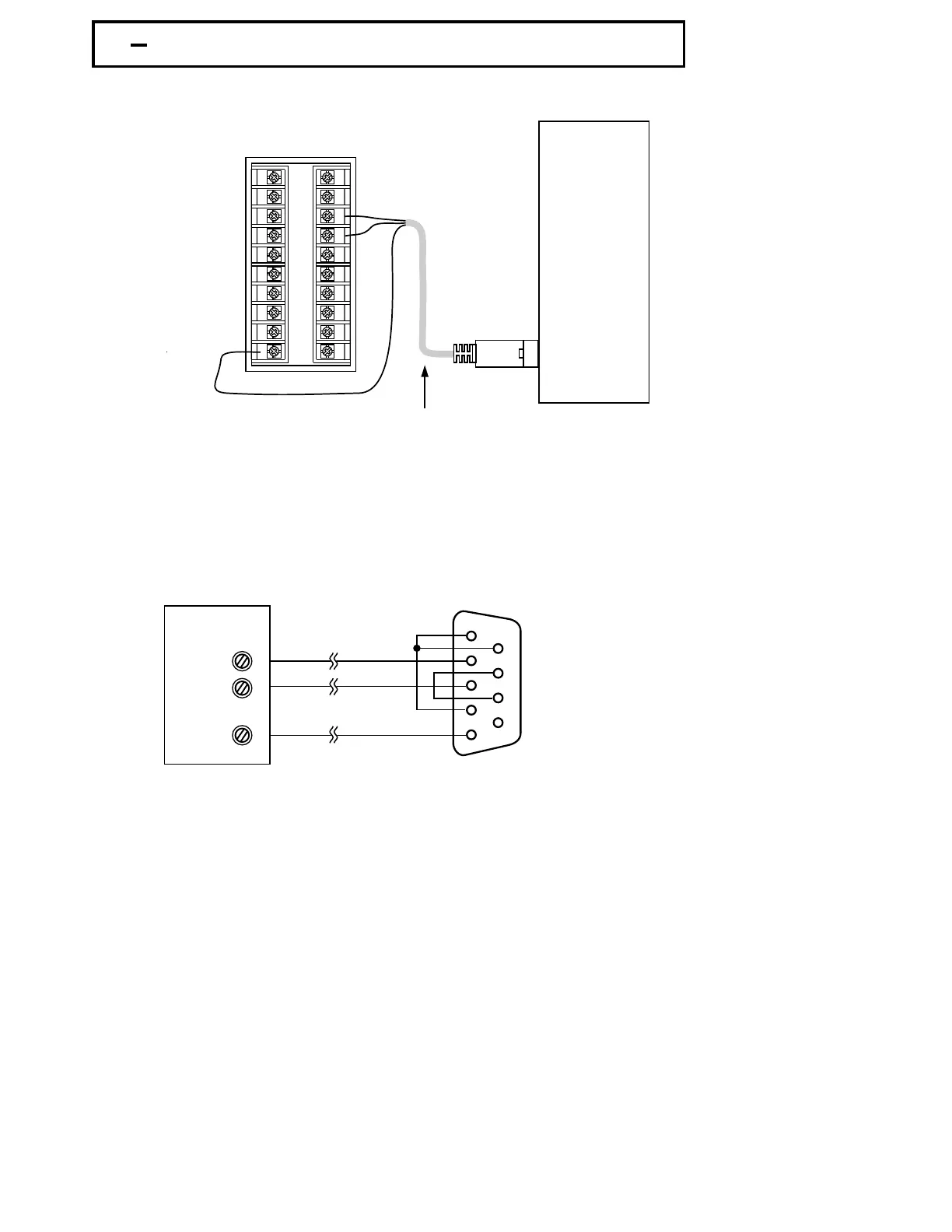
If you use a conventional 9-pin RS-232 cable instead of CC94-1, the cable must
be modified according to the following circuit diagram.
If you use a conventional 9-pin RS-232 cable instead of CC94-1, the cable must
be modified according to the following circuit diagram.
1
2
3
4
5
6
7
8
9
FDC-8300
TX1
TX1 RD
13
14
10
TX2
TX2 TD
COM
COM GND
Female DB-9Female DB-9
To DTE ( PC ) RS-232 PortTo DTE ( PC ) RS-232 Port
1 DCD
2R
D
3T
D
4DTR
5 GND
6DSR
7 RTS
8CTS
9RI
1 DCD
2 RD
3 TD
4 DTR
5 GND
6 DSR
7 RTS
8 CTS
9 RI
Figure 2.21
Configuration
of
RS-232
Cable
Figure 2.21
Configuration of RS-232
Cable
UM83001A-August-2024
24
1
2
3
4
5
6
7
8
9
10
11
12
13
14
15
16
17
18
19
20