9 SEAT WIDTH AND DEPTH
540 –UM 1024402 REV08 10/2013 22 Capella / Capella 45
9 Seat Width and Depth
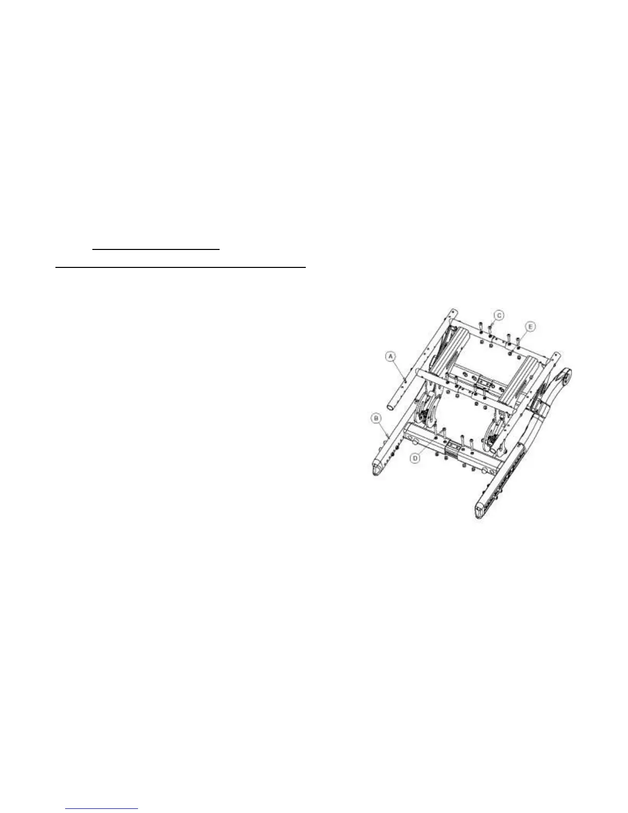
Changing Seat Width [Figure 9, Figure 10, Figure 11]
1. Start with either the left side or right side of the wheelchair and
remove four (4) 1/4-20 x 1.25” screws (‘C’) and four(4) 1/4-20
nuts(‘E’) from the seat frame(‘A’) (2 in the front and 2 in the back)
on the same side.
2. Proceed to the lower frame (‘B’) and remove four (4) 1/4-20 x
2.25” screws (‘D’) and four (4) 1/4-20 nuts(‘E’) (2 in the front and
2 in the back) on the same side.
3. Grasp the seat frame and lower frame and pull towards oneself
observing the holes being uncovered. The Frame can be adjusted
by 2” on each side which is 5 holes @ 1/2” center to center on
each side. For example to increase the width of the chair by 2”
overall each side has to be increased by 1”.
4. Place the screws and nuts in their respective holes and hand
tighten. The 1/4-20 x 1.25” screws attach to the seat frame while
the 1/4-20 x 2.25” screws attach to the lower frame. See Figure
5b and 5c for hole locations on the crossbar and seat frame.
5. Now start with the side (either left or right) which remains to be
adjusted and remove four (4) 1/4-20 x 1.25” screws(‘C’) and four
(4) 1/4-20 nuts(‘E’) from the seat frame(‘A’) as well as remove
four (4) 1/4-20 x 2.25” screws(‘D’) and four (4) 1/4-20 nuts (‘E’)
from the lower frame.
6. Repeat step # 3 and #4 and check the overall size of the chair
before fully tightening the screws and nuts.
 Loading...