Chapter 8 -- Measurement of Small Signals--Measurement System Model and Physical Limitations
8 - 2
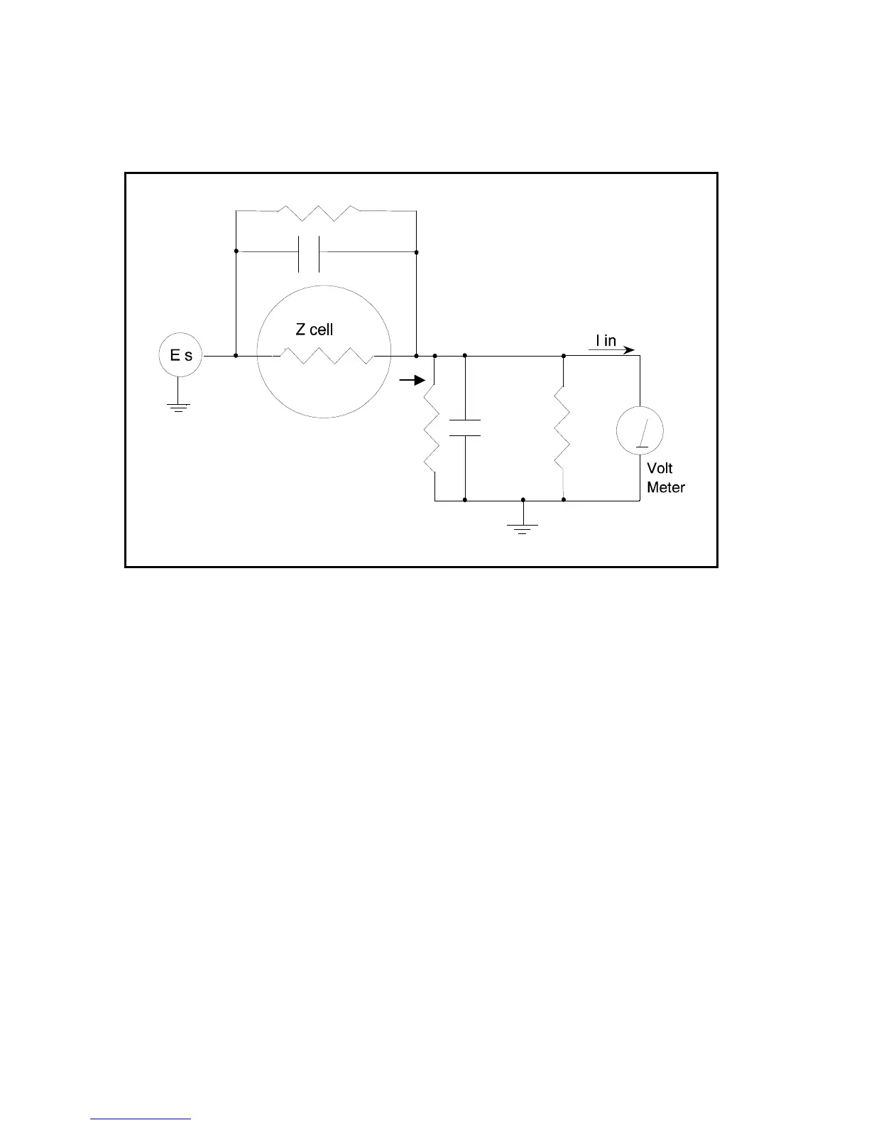
Figure 8-1
Equivalent Measurement Circuit
Icell
C shunt
R shunt
R in
Rm
Unfortunately, technology limits high impedance measurements because:
• Current measurement circuits always have non-zero input capacitance, i.e. C
in
> 0.
• Infinite R
in
cannot be achieved with real circuits and materials.
• Amplifiers used in the meter have input currents, i.e. I
in
> 0.
• The cell and the potentiostat create both a non-zero C
shunt
and a finite R
shunt
.
Additionally, basic physics limits high impedance measurements via Johnson noise, which is the inherent
noise in a resistance.
Johnson Noise in Z
cell
Johnson noise across a resistor represents a fundamental physical limitation. Resistors, regardless of
composition, demonstrate a minimum noise for both current and voltage, per the following equations:
E = (4 k T R δF)
1/2
I = (4 k T δF / R)
1/2
Where;
k = Boltzman's constant 1.38x 10
-23
J/
o
K
T = temperature in
o
K
δF = noise bandwidth in Hz
R = resistance in ohms.
For purposes of approximation, the Noise bandwidth, δF, is equal to the measurement frequency. Assume
a 10
11
ohm resistor as Z
cell
. At 300
o
K and a measurement frequency of 1 Hz this gives a voltage noise of