Appendix B -- Interface 1000 Cell Connector--Floating Operation
10 - 1
Appendix B -- Interface 1000 Cell Connector
Chapter 4 describes the connections between a cell cable and an electrochemical cell. This appendix
describes the other end of the cell cable.
Multiple pins assigned to the same signal are connected together on the Interface 1000’s Potentiostat
board. If you need to connect this signal outside the Interface 1000, you need a wire connected to any
one of the D connector pins.
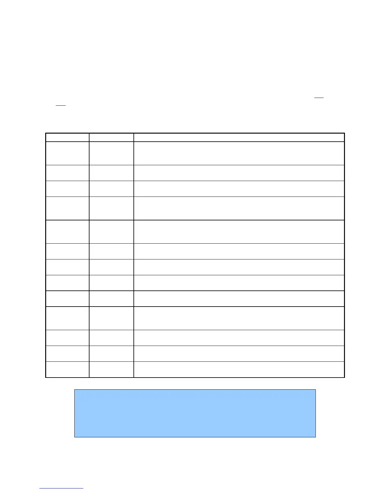
Table B-1
Cell Connector
Pin(s) Signal Name Use
1 Working
Sense
Connected to the working electrode in most cases (see Chapter 4). This lead
has a 261 Ohm resistor in the cell end of the cable. Custom cell cables are
likely to require a similar resistor.
2, 14 WS Shield The shield for the working sense input. Driven to the same potential as Pin 1.
Left open at the cell end of the cell cable.
3, 4, 15, 17 Reference
Shield
The shield for the reference electrode input. Driven to the same potential as
Pin 16. Left open at the cell end of the cell cable.
5, 7, 10, 11,
18, 19, 22,
24
Ground The potentiostat's floating ground. Can be used to shield the cell if very low
currents need to be measured. Also used as a shield for the counter electrode
cable.
6 Counter Sense
With an Interface 1000, used to sense the potential of the counter electrode.
Allows accurate ZRA mode even with significant cell current through counter
lead’s resistance.
8 CBL_ID1 One of 4 cable ID bits. Used to identify the type of cell cable attached to the
unit. Pull to a logic High through a resistor. Ground to set the bit low.
9 CBL_ID2 One of 4 cable ID bits. Used to identify the type of cell cable attached to the
unit. Pull to a logic High through a resistor. Ground to set the bit low.
12, 25 Work
Shield
The shield for the working electrode input. Connected to Floating Ground.
Left open at the cell end of the cell cable.
13 Working
Electrode
Connected to the working electrode. The cell current flows through this pin.
16 Reference
Electrode
Connected to the reference electrode in most cases (see Chapter 4). This lead
has a 261 Ohm resistor in the cell end of the cable. Custom cell cables are
likely to require a similar resistor.
20 CBL_ID0 One of 4 cable ID bits. Used to identify the type of cell cable attached to the
unit. Pull to a logic High through a resistor. Ground to set the bit low.
21 CBL_ID3 One of 4 cable ID bits. Used to identify the type of cell cable attached to the
unit. Pull to a logic High through a resistor. Ground to set the bit low.
23 Counter
Electrode
Connected to the cell's counter electrode. The cell current flows through this
connection.
Caution
Designing cell cabling for a 1 MHz potentiostat is not a trivial task. Gamry
Instruments does not recommend user designed cables (except as a last resort). In
many cases we can build a custom cable to meet your specific needs. We’ll also be
happy to discuss your cabling requirements and give you assistance if you must
design and build your own cell cable.