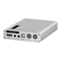
Computer module »DP-HR-CPU-Fiber-MC2-UC«
Computer and console modules (DP-HR) · 50
Connecting the second first matrix switch
Trans. 2|Channel 1|Tx: Insert the LC plug of a compatible optical fibre cable. Connect
the other end of the cable to the
Rx interface of a Dynamic Port provided at the second
matrix switch.
Trans. 2|Channel 1|Rx: Insert the LC plug of a compatible optical fibre cable. Connect
the other end of the cable to the
Tx interface of the same Dynamic Port provided at the
second matrix switch.
Trans. 2|Channel 2|Tx: Insert the LC plug of a compatible optical fibre cable. Connect
the other end of the cable to the
Rx interface of another Dynamic Port provided at the
second matrix switch.
Trans. 2|Channel 2|Rx: Insert the LC plug of a compatible optical fibre cable. Connect
the other end of the cable to the
Tx interface of the same Dynamic Port provided at the
second matrix switch.
Power supply
Power In: Insert the power pack’s connection cable to this interface.
Start-up
Connect the power cable to the power pack and a power socket.
The computer module starts as soon as it is supplied with power. During start-up,
the channels are automatically grouped (see below).
Automatic grouping of channels
When operating the computer module for the first time, the matrix switch recognises
the main channel and the computer module’s additional channel. The channels are
automatically added to a channel group.
ADVICE:
You can also connect the computer module directly to up to two compatible
console modules.
NOTE:
You can adjust any manually or automatically created channel group.
More information about channel groups is given in the separate manuals of the
matrix switch web applications.
 Loading...