GAT NET.Lock 7000 System
Electrical Connection
www.gantner.com
HB_GAT-NETLOCK7000--EN_30
23
4. ELECTRICAL CONNECTION
This chapter describes the electrical connection of a GAT NET.Lock 7000 and also of the control units GAT NET.Con-
troller S 7000 and GAT NET.Controller M 7000.
Cable connection must only be done in powerless state and only by trained and specialised personnel.
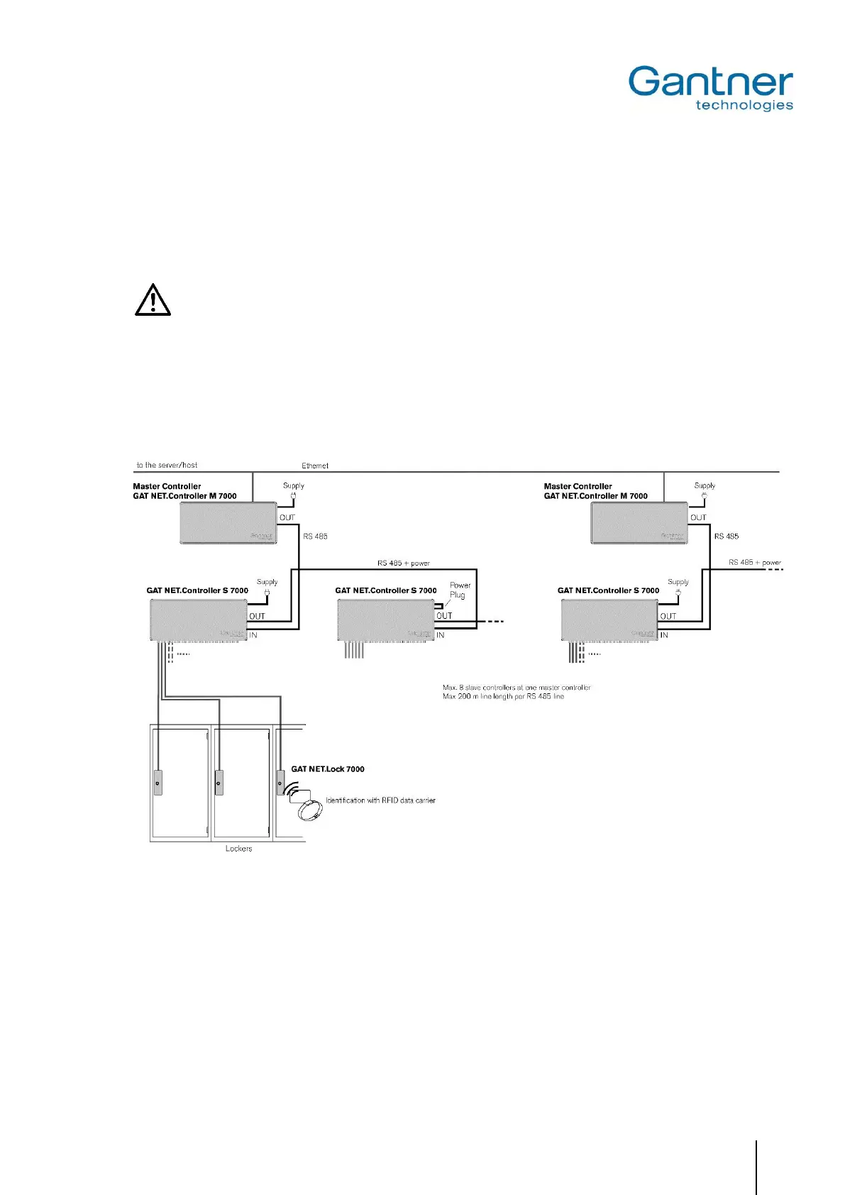
4.1 System Structure
The GAT NET.Lock 7000 are always connected to the slave controllers GAT NET.Controller S 7000. The slave con-
trollers are in turn networkable via serial RS 485 interface and are connected to a master controller GAT NET.Con-
troller M 7000. The master controllers are connected via Ethernet to a host computer or server.
Figure 4.1 - GAT NET.Lock 7000 system structure
 Loading...