GAT NET.Lock 7000 System
Electrical Connection
28
HB_GAT-NETLOCK7000--EN_30
www.gantner.com
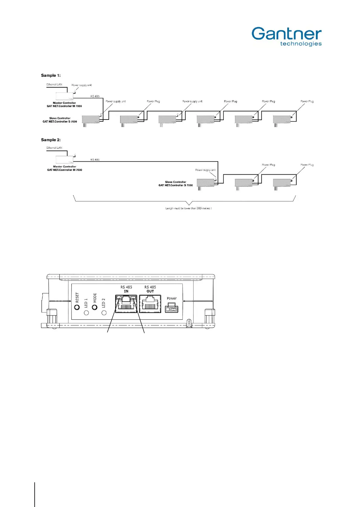
Figure 4.9 - Examples for power supply
4.3.4 LED Signals and Buttons
For the display of the operating state and to start certain functions various LED indicators and buttons are provided
on the GAT NET.Controller S 7000.
Figure 4.10 - LEDs and buttons provided at the GAT NET.Controller S 7000
LEDs
- RS 485 IN (yellow): The connection with the master controller has been established.
- RS 485 IN (green): RS 485 communication is active.
- LED 1 (blue): Lock activated/controlled.
- LED 2 (green/red): See "5.5. Status Information at GAT NET.Controller S 7000 and GAT NET.Controller M 7000".
Buttons
- RESET: 1. See "5.3. Restart a Controller GAT NET.Controller S 7000 or GAT NET.Controller M 7000"
2. See "5.4. Delete Configuration Parameters of a Controller (= Reset to Default Settings) "
- MODE: See "5.1 Antenna Adjustment of the GAT NET.Lock 7000"
 Loading...