GAT NET.Lock 7020 System
Installation
www.gantner.com
HB_GAT-NETLOCK7020--EN_12
33
3.12
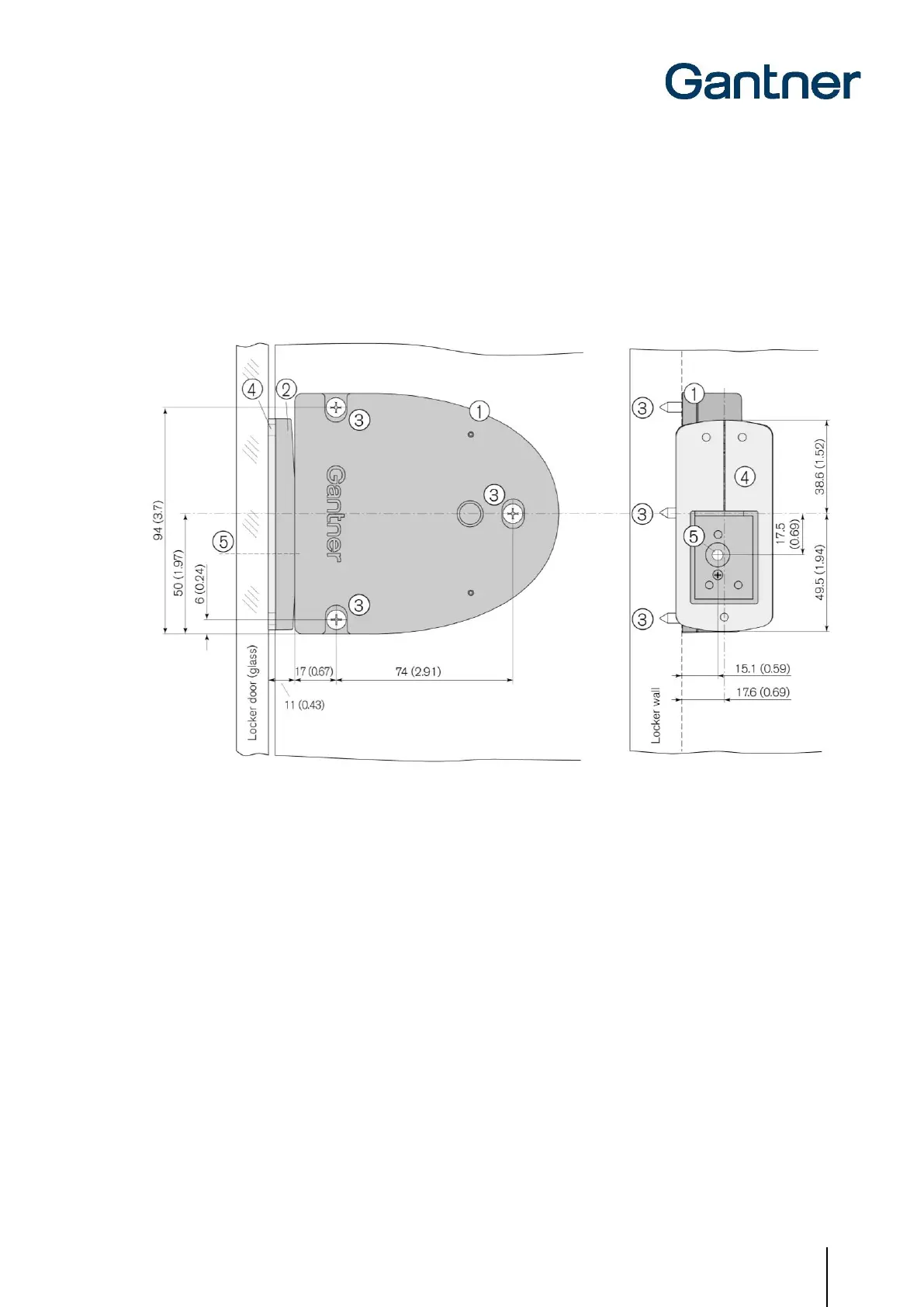
Installation in Lockers with Glass Doors
The GAT NET.Lock 7020 can be installed on the left or right side of the inner locker wall depending on whether it is
a right or left-hinged locker door (see “3.7. Definition of the Door Hinge (Right or Left Door)). The GAT NET.Lock Bolt
Set 7320 with the metal support attaches to the inner side of the locker door using adhesive. A void in the printing on
the locker door or door label may be necessary for the status LED to be visible. See in Figure 3.13 and the following
installation instructions.
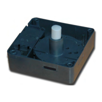
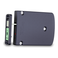
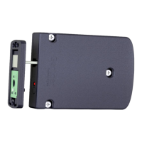
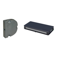
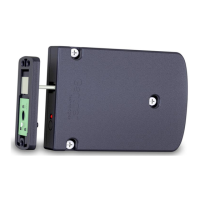
1. GAT NET.Lock 7020
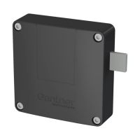
2. GAT NET.Lock BoltSet 7320
3. 3 x mounting holes for the GAT NET.Lock 7020
4. Metal support for adhering the GAT NET.Lock BoltSet 7320 (the metal support is included with the GAT NET.Lock
BoltSet 7320 and is delivered attached to the bolt set).
5. LED position
Figure 3.13 - Installation in a locker with glass door (right-hinged)
 Loading...