GAT NET.Lock 7020 System
Configuration and Operation
52
HB_GAT-NETLOCK7020--EN_12
www.gantner.com
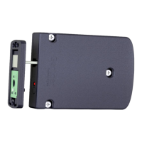
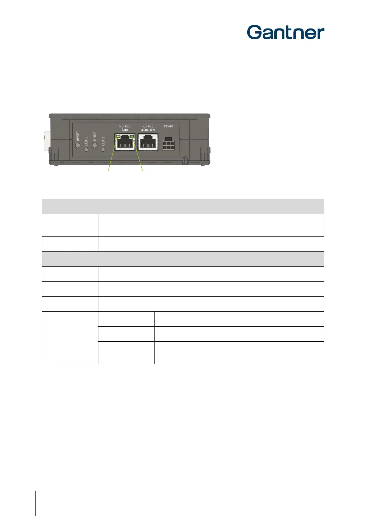
5.4.2 Master Controller
To display different operating states and to start certain functions, the following LED indicators and buttons are
provided on the GAT NET.Controller M 7020.
Figure 5.5 - LEDs and buttons on the GAT NET.Controller M 7020
1. See "5.2. Restarting a Controller"
2. See "5.3 Resetting a Controller to the Default Settings"
The connection with the sub controller has been established
RS-485 communication active
Emergency operation (no connection to server/software)
Normal operation (connection to server/software OK)
Bootloader mode (a firmware update is currently being loaded or
there is no firmware installed)
Table 5.2 - Buttons and LEDs of the GAT NET.Controller M 7020 master controller
 Loading...