Do you have a question about the Gantner GAT SMART.Lock 7000 System and is the answer not in the manual?
Manual contains installation, operation, and system component info.
Contact details for system inquiries and support.
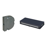
Lists and illustrates all components of the GAT SMART.Lock 7000 system.
Information on planning and ordering system components.
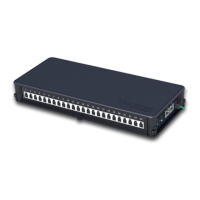
Details on the central reader for user identification and locker control.
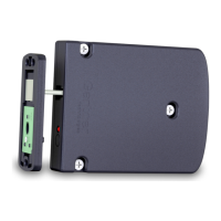
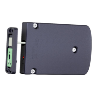
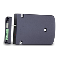
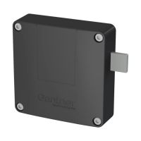
Explains the core functionality and application of the GAT SMART.Lock 7001.
Defines key terms used throughout the manual for clarity.
Explains how to identify left vs. right-hinged locker doors for installation.
Provides critical dimensions for hardware parts and installation.
Specifies the minimum door width required for lock installation.
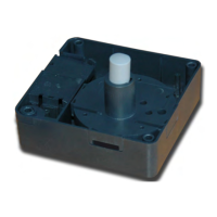
Details the dimensions and mounting hole information for the lock housing.
Provides dimensions for the door shackle and associated mounting plates.
Highlights crucial measurements for correct lock and shackle placement.
Step-by-step guide for mounting the lock on the interior of the locker door.
Instructions for installing the lock within the locker's intermediate wall.
Details how to mount the door shackle using a door plate and distance plate.
Explains the security bolt and its removal after installation.
Lists important considerations and precautions during the installation process.
Guidance on performing a test installation and functional testing before serial production.
Procedure for replacing the lock and components after a forced opening.
Overview of how the GAT SMART.Lock system components connect and network.
Details on connecting the lock using specific cables and extension options.
Specifies the power requirements for the GAT SMART.Lock 7001.
Explains the locking status signal and its requirements.
Describes connecting the GAT SMART.Lock 7001 to the slave controller.
Details connecting the locks to the slave controller via MOLEX connectors.
Explains RS 485 and Ethernet networking for slave controllers.
Details power supply options and connection for the slave controller.
Explains the LEDs and buttons on the GAT SMART.Controller S 7000 for status indication.
Details connecting slave controllers to the master controller and Ethernet.
Describes connecting slave controllers to the master controller via RS 485.
Explains networking the master controllers and connecting to PC/server via Ethernet.
Details power supply connection for the GAT NET.Controller M 7000.
Explains the LEDs and buttons on the GAT NET.Controller M 7000.
Explains using COM converters for RS 485 to Ethernet.
Details connecting the central reader for RFID data carrier identification.
Connecting slave controllers to the central reader via RS 485 and Ethernet.
Specifies power supply requirements for the central reader.
How to configure the central reader using GAT Configuration Manager software.
Steps to directly configure a terminal or manage projects.
Lists available settings and their default values for the central reader.
How to configure MOXA COM Converters via Ethernet using NPort Suite.
How users lock and unlock lockers via the system.
Overview of the GAT Relaxx software for system operation and monitoring.
Displays system hardware, channels, controllers, and locker status in GAT Relaxx.
Visualizes locker areas, status, and actions within the GAT Relaxx system.
Detailed technical specifications for the GAT SMART.Lock 7001.
Technical specifications for the master controller.
Technical specifications for the slave controller.
| Type | Electronic Lock |
|---|---|
| System | GAT SMART.Lock 7000 |
| Connectivity | Wireless |
| Power Supply | Battery |
| Battery Life | Up to 2 years |
| IP Rating | IP54 |
| Technology | RFID |
| Communication | Bluetooth |
| Application | Indoor |