GAT SMART.Lock 7000 System
Electrical Connection
www.gantner.com
HB_GAT-SMARTLOCK7000--EN_10
25
4. ELECTRICAL CONNECTION
This chapter describes the electrical connections of the GAT SMART.Lock 7001. It also includes a description of the
connection and networking of the GAT SMART.Controller S 7000.
Attention: Cable connection must only be done in a powerless state and only by trained, specialised per-
sonnel.
4.1 System Structure
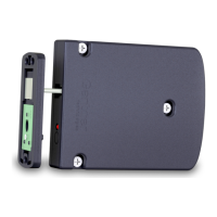
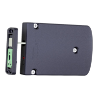
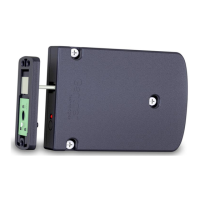
The GAT SMART.Lock 7001 locks connect to the GAT SMART.Controller S 7000 controller units. The controller
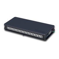
units are in turn networkable via RS 485 and can be connected through a COM Server or Master Controller to a
server over Ethernet. Depending on the system requirements, different options are available to control (lock & un-
lock) the individual GAT SMART.Lock 7001 locks. Lock functions can be controlled by a PC running system control
software, or via a central reader terminal where users can identify themselves and where only the central reader
has autonomous control of the corresponding locker.
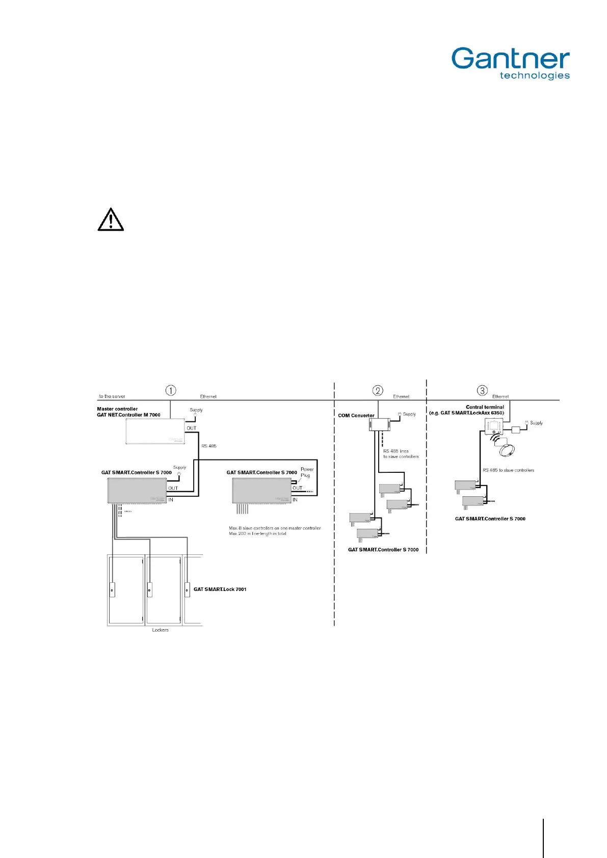
Figure 4.1 - System structure of a GAT SMART.Lock system
: The GAT NET.Controller M 7000 master controller is used to control the GAT SMART.Lock 7001. For larger
systems, several master controllers may be used together with each master controller able to control up to 8
slave controllers.
: The GAT SMART.Lock 7001 locker locks are connected to a PC/server via a COM converter (e.g., MOXA) via
Ethernet. The control of the lockers is performed by a PC running system control software.
: System users can identify themselves at a central reader terminal with their RFID data carriers and unlock the
corresponding locker.
 Loading...