GAT SMART.Lock 7000 System
Electrical Connection
26
HB_GAT-SMARTLOCK7000--EN_10
www.gantner.com
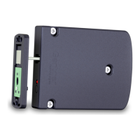
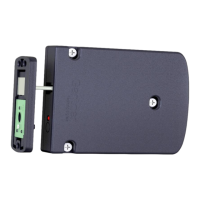
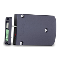
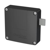
4.2 Cable Connection of the GAT SMART.Lock 7001
A 4m long connection cable (GAT NET.Lock Cable 4m, Part No. 321826) is supplied with the lock. This cable is
used to connect the GAT SMART.Lock 7001 to a GAT SMART.Controller S 7000 control unit. The cable comes with
a 4-pin MOLEX connector of the Micro-Fit 3.0
TM
type at both ends.
Figure 4.2 - Cable connection at the GAT SMART.Lock 7001
If the standard connection cable is too short, an additional 4 m extension cable (GAT NET.Lock Cable 4m) can be
used. To connect both cables, use a GAT NET.Lock Connector.
4.2.1 Power Supply
The GAT SMART.Lock 7001 requires a 24 V DC power supply (for more details, please refer to the technical data)
to control the unlocking (lifting magnet). The unlocking occurs when power is applied.
4.2.2 Locking Return Message
A potential-free contact in the GAT SMART.Lock 7001 signals the locking status. If the contact is closed, the lock is
locked (i.e., the locker door is closed).
Attention: The return message contact must be continuously supplied with an amperage of at least 1 mA (at
24 V DC, please refer to the technical data).
 Loading...