GAT SMART.Lock 7000 System
Electrical Connection
32
HB_GAT-SMARTLOCK7000--EN_10
www.gantner.com
4.4 Connection of the GAT NET.Controller M 7000 Master Controller
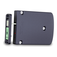
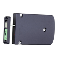
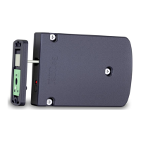
4.4.1 Connection of the GAT SMART.Controller S 7000 slave controller to the Master Controller
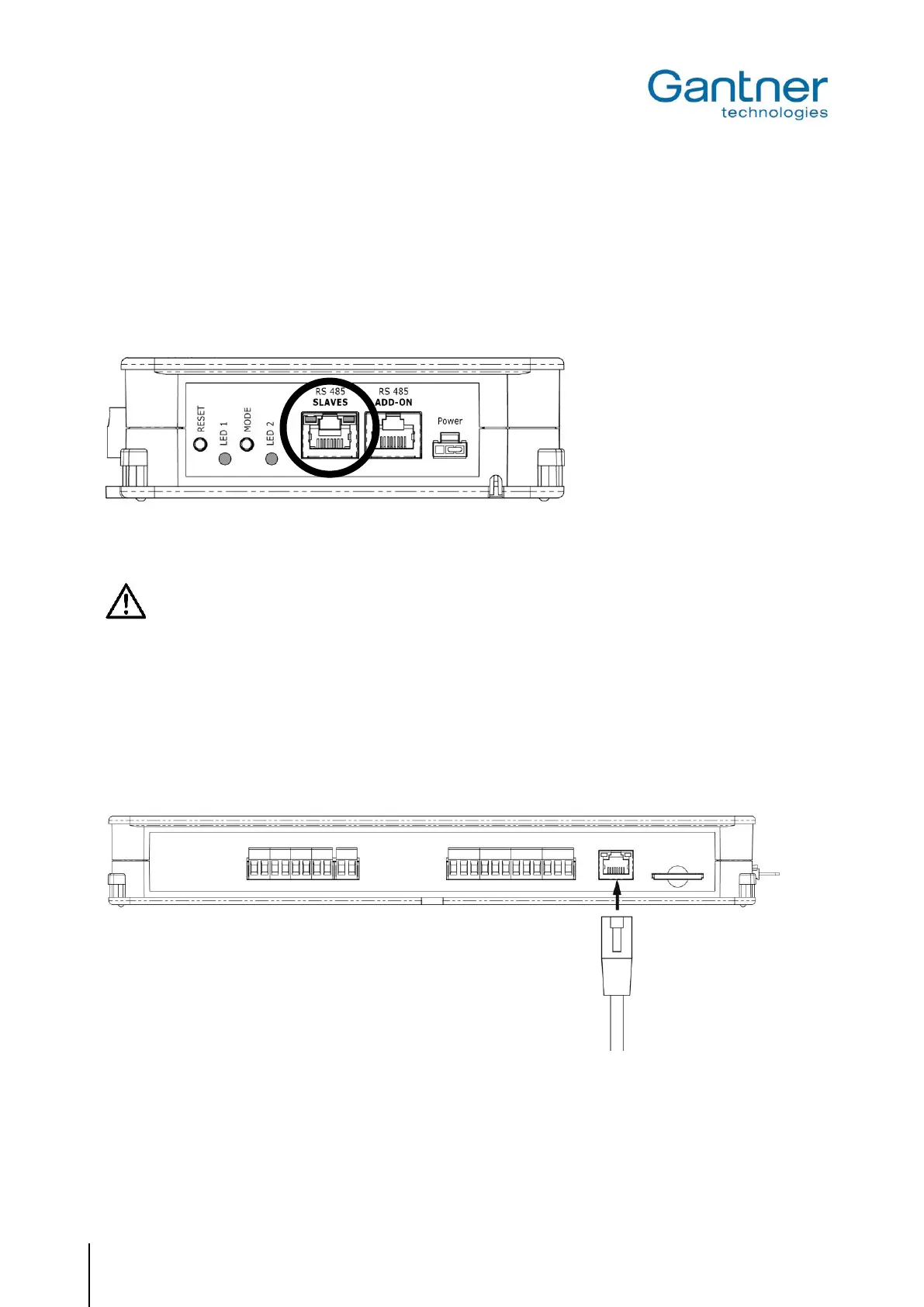
The slave controllers are connected to the master controllers via RS 485 using RJ 45 plugs. The connection must
be made through the "RS 485 SLAVES" socket.
Figure 4.11 - Connection of the GAT SMART.Controller S 7000 to the GAT NET.Controller M 7000
Observe the following values for the number of connectable controllers per interface:
- A maximum of 8 slave controllers per RS 485 line
- Maximum length of one RS 485 line = 200 m
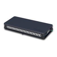
4.4.2 Ethernet Connection
The networking of several GAT NET.Controller M 7000, as well as the connection of the master controllers to a
PC/server is performed via Ethernet. The Ethernet line is connected via RJ 45 plugs.
Figure 4.12 - Connection of the GAT NET.Controller M 7000 to Ethernet
 Loading...