GAT SMART.Lock 7000 System
Electrical Connection
www.gantner.com
HB_GAT-SMARTLOCK7000--EN_10
31
4.3.4 Signalling
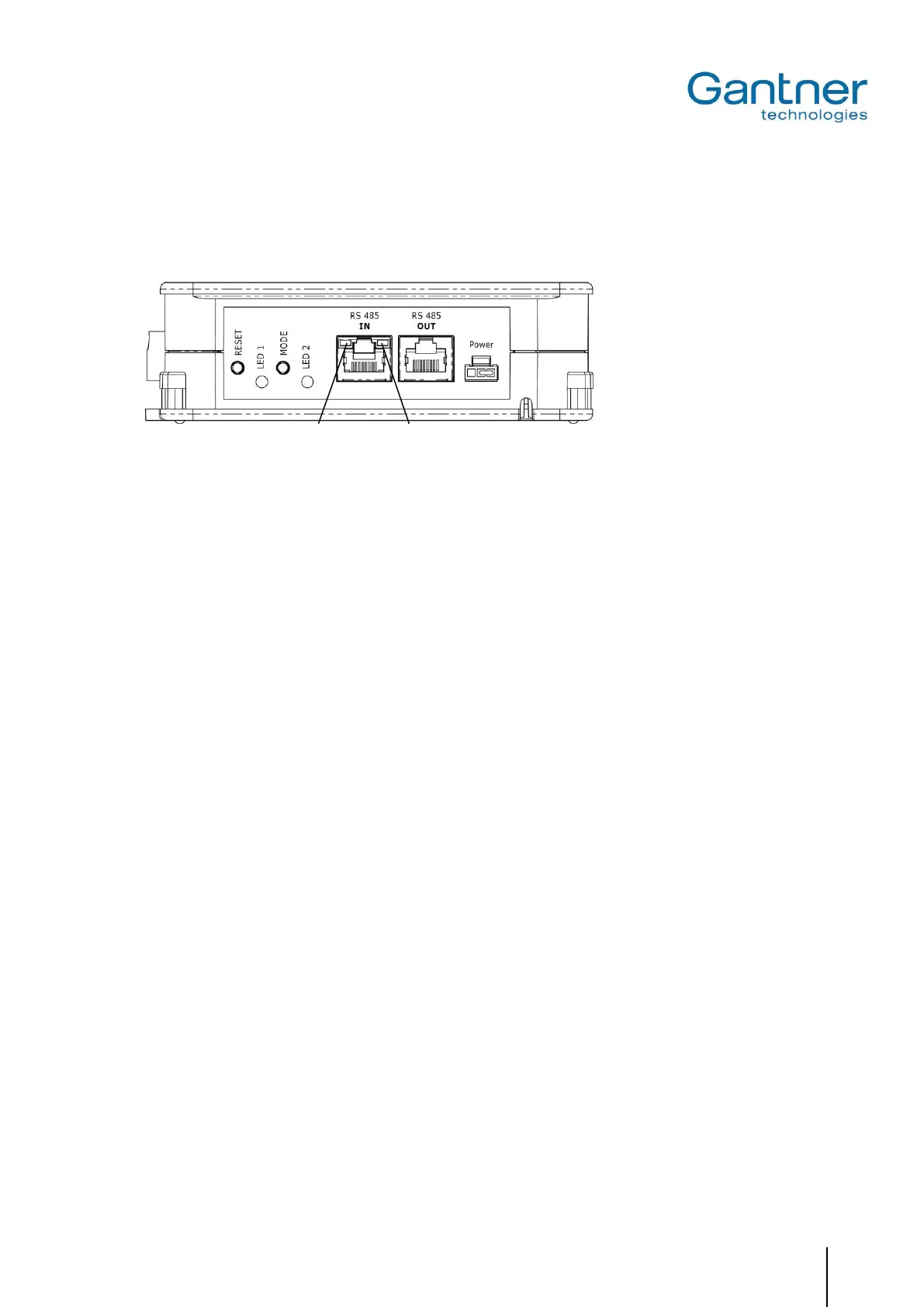
To display its operating state, various LED indicators are provided on the GAT SMART.Controller S 7000.
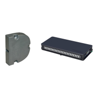
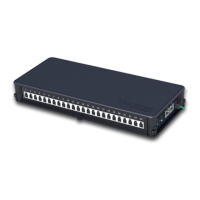
Figure 4.10 - LEDs and buttons provided on the GAT SMART.Controller S 7000
LEDs
- RS 485 IN (yellow): The connection with the master controller has been established
- RS 485 IN (green): RS 485 communication is active
- LED 1 (blue): Lock activated/controlled
- LED 2 (green/red): Status information
Buttons
- RESET: Reset to factory settings
- MODE: Currently no function, reserved for future applications
 Loading...