GAT SMART.Lock 7000 System
Electrical Connection
www.gantner.com
HB_GAT-SMARTLOCK7000--EN_10
29
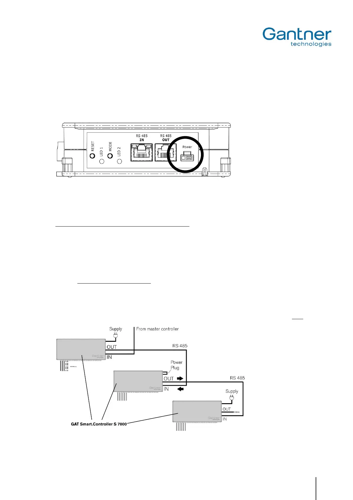
4.3.3 Power Supply
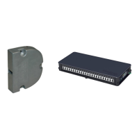
The GAT SMART.Controller S 7000 is connected via an external power supply unit (GAT NET.Power Supply 100-
240V, see “7. Technical Data”) to a mains power supply outlet. The power supply is connected to the MOLEX plug
on the side of the controller. A suitable power cord for the power supply must be ordered separately. There are dif-
ferent power cables available depending on the country of use (see “2.1. System Parts”).
Figure 4.7 - Connection of the power supply on the GAT SMART.Controller S 7000
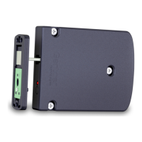
The power supply unit may be placed inside the designated storage section on the side of the slave controller.
Two different options for power connection are available:
1. A power supply can be individually connected to each slave controller. A maximum of 8 slave controllers can be
connected per RS 485 line (max. line length = 200m).
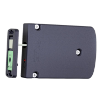
2. A power supply can be connected to one or a few slave controllers that then supply the remaining slave control-
lers via the RS 485 cable. In this case, the following points must be adhered to:
- The “power plug” must be inserted for the slave controllers that are not directly connected to a power supply.
A maximum of 4 slave controllers can be supplied in this way.
- If there are more than 4 slave controllers on an RS 485 line, another power supply must be connected to the
5
th
slave controller.
- The 1
st
slave controller connected after the master controller must always be connected to a power supply.
- A maximum of 8 slave controllers can be connected per RS 485 line.
- Pay attention to the direction of the power supply. Power is only distributed from the “RS 485 OUT” socket.
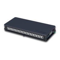
Figure 4.8 - Power transmission via RS 485 Interface
 Loading...