GAT SMART.Lock 7000 System
Electrical Connection
www.gantner.com
HB_GAT-SMARTLOCK7000--EN_10
33
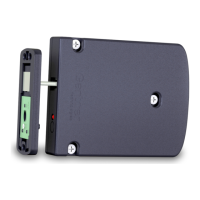
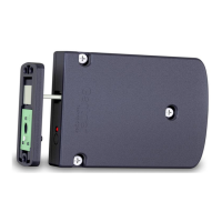
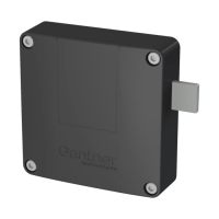
4.4.3 Connection of the Power Supply
The GAT NET.Controller M 7000 is connected via an external power supply unit (GAT NET.Power Supply 100-
240V, see “7. Technical Data”) to a mains power supply outlet. The power supply is connected to the MOLEX plug
on the side of the controller. A suitable power cord for the power supply must be ordered separately. There are dif-
ferent power cables available depending on the country of use (see “2.1. System Parts”).
Figure 4.13 - Power supply on the GAT NET.Controller M 7000
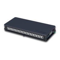
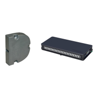
The power supply unit may be placed in the designated storage section inside the master controller.
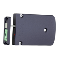
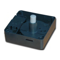
4.4.4 Signalling
For display of the operating state, various LED indicators are provided on the GAT NET.Controller M 7000.
Figure 4.14 - LED and buttons provided on the GAT NET.Controller M 7000
LEDs
- RS 485 IN (yellow): The connection with the slave controller has been established
- RS 485 IN (green): RS 485 communication is active
- LED 1 (blue): Lock activated/controlled
- LED 2 (green/red): Status information
Buttons
- RESET: Reset to factory settings
- MODE: Currently no function, reserved for future applications
 Loading...