GAT SMART.Lock 7000 System
Electrical Connection
www.gantner.com
HB_GAT-SMARTLOCK7000--EN_10
35
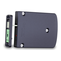
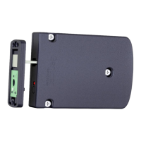
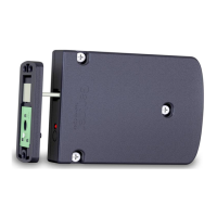
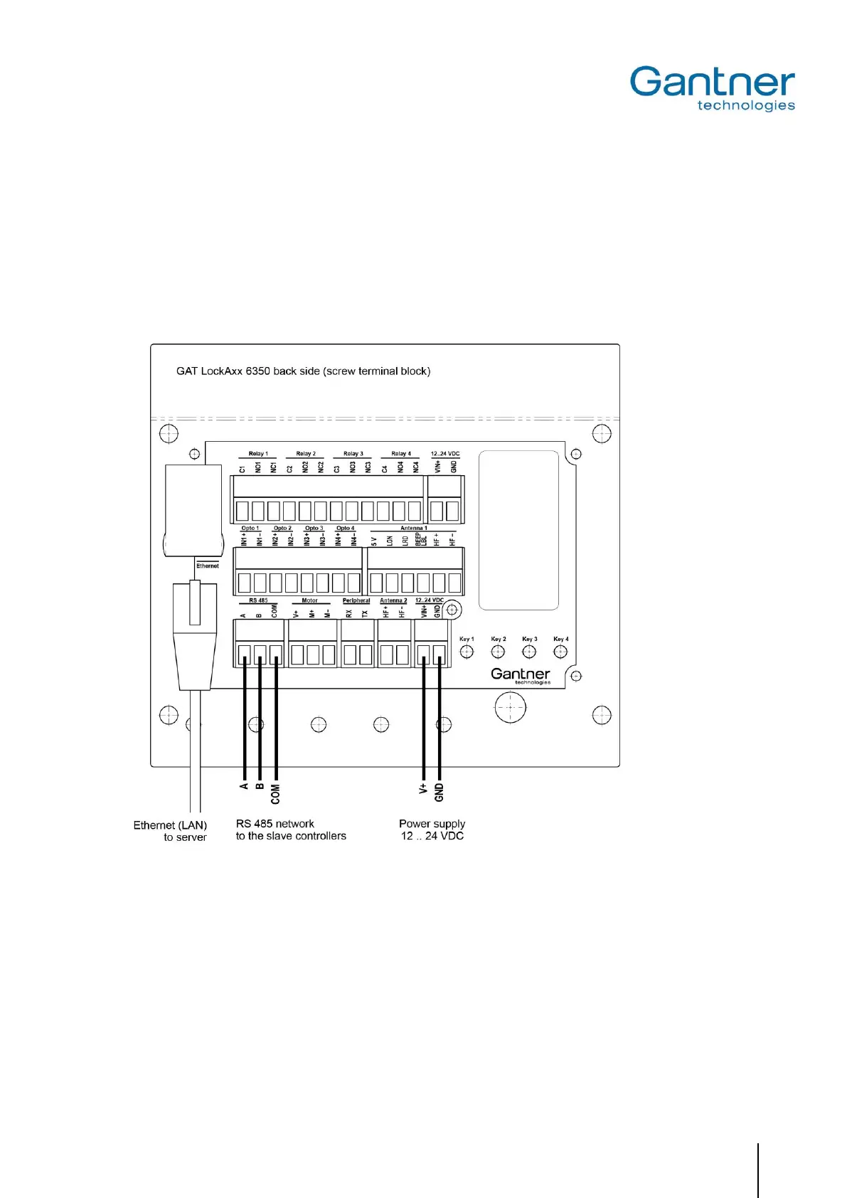
4.6.1 Connection of the GAT SMART.Controller S 7000 Slave Controller and Ethernet
The slave controllers are connected to the GAT SMART.LockAxx 6350 via RS 485 using screw terminals. The con-
nection must be realised at the RS 485 socket.
Note: Upon delivery, the GAT SMART.LockAxx Controller Cable (No. 618027) for connection of the slave control-
lers is already connected at the GAT SMART.LockAxx 6350.
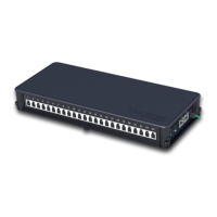
The connection to the Ethernet LAN network is made via the RJ 45 connector and the "Ethernet" jack.
Figure 4.16 - Connection of the GAT SMART.LockAxx 6350 central reader
4.6.2 Connection of the Power Supply
The GAT SMART.LockAxx 6350 central reader requires a U
DC
12/24 V power supply (voltage range from 10 to 28
V). The average power consumption is 12 W.
 Loading...