GAT SMART.Lock 7000 System
Operation
www.gantner.com
HB_GAT-SMARTLOCK7000--EN_10
49
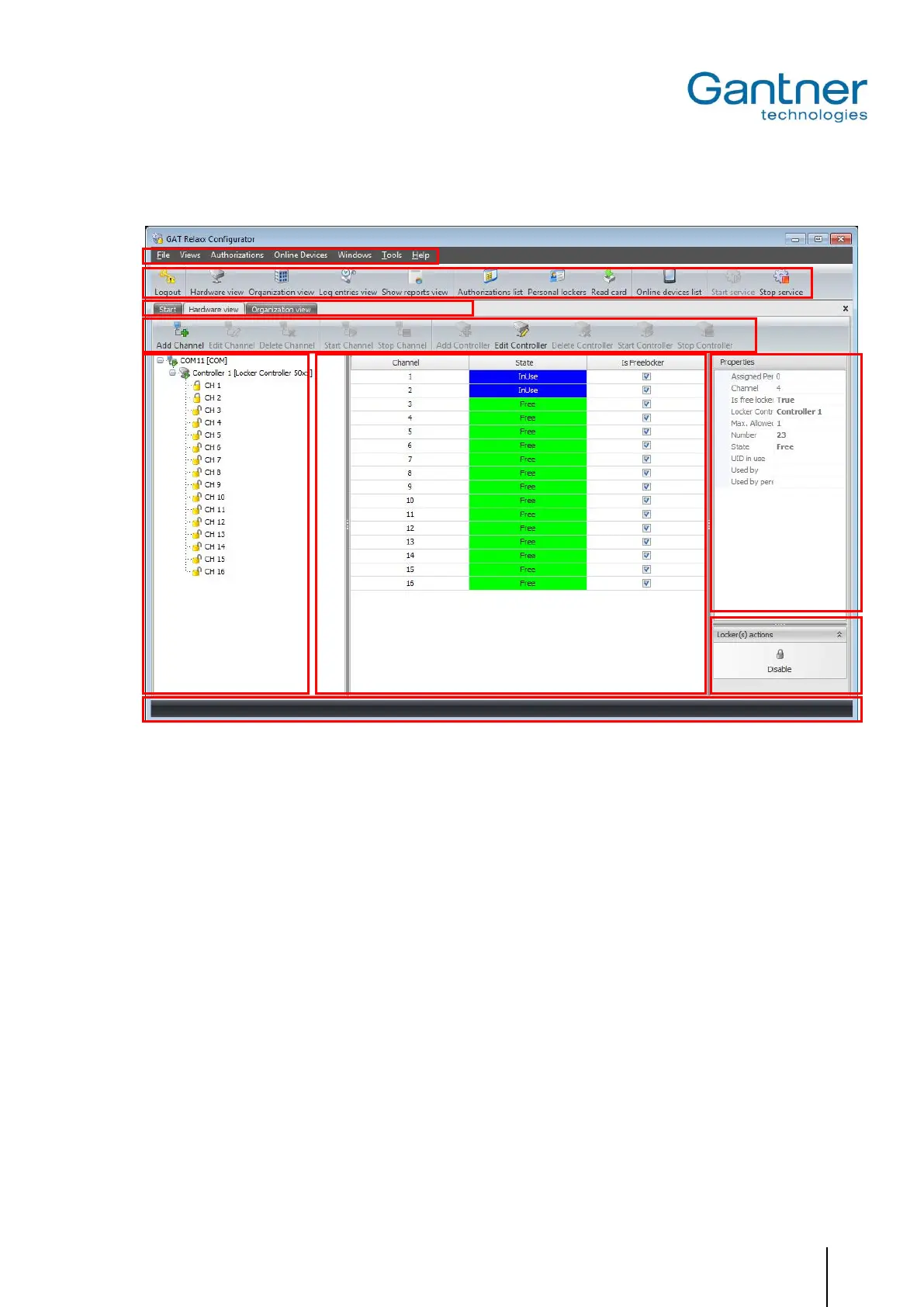
Hardware View
Figure 6.1 - GAT Relaxx – Hardware View
The hardware view is divided into the following areas:
1 - Main menu: Access to all GAT Relaxx functions by selecting the corresponding menu points.
2 - Symbol bar: Fast access to the main functions.
3 - Switch user interface: Next to the "Start" tab, a tab is displayed for each user interface. Several configura-
tions and user tabs can be created.
4 - Selective symbol bar: Fast access to the main functions of the currently selected user interface.
5 - System overview: Hardware of the entire system is defined here. Communication channels and con-
nected controllers can be added and the lockers used can be defined per controller.
6 - Locker overview: Here, the lockers (GAT SMART.Lock 7001) of the controller selected on the left are
displayed together with their current status.
7 - Information area: Here, the information regarding the locker selected under (6) is displayed.
8 – Locker actions: Different locker actions can be performed in this section, e.g., the action “Open all
lockers” will send a command to open all connected lockers.
9 - Status bar: The status bar displays various information regarding the GAT Relaxx system such
as:
- Whether the GAT Relaxx service is running and if the connection is OK.
- The system operation mode (online/offline).
- Whether a USB driver is installed. This is required if a data carrier read/write de-
vice (e.g., GAT Writer) is used with the system.
- Information about the currently logged-in user.
 Loading...