13-20-604 Page 11
SECTION 2
INSTALLATION
GENERAL - On receipt of the unit, check for any damage that may have been incurred during transit.
Report any damage or missing parts as soon as possible.
Do not electric weld on the compressor or base; bearings can be damaged by
passing of current.
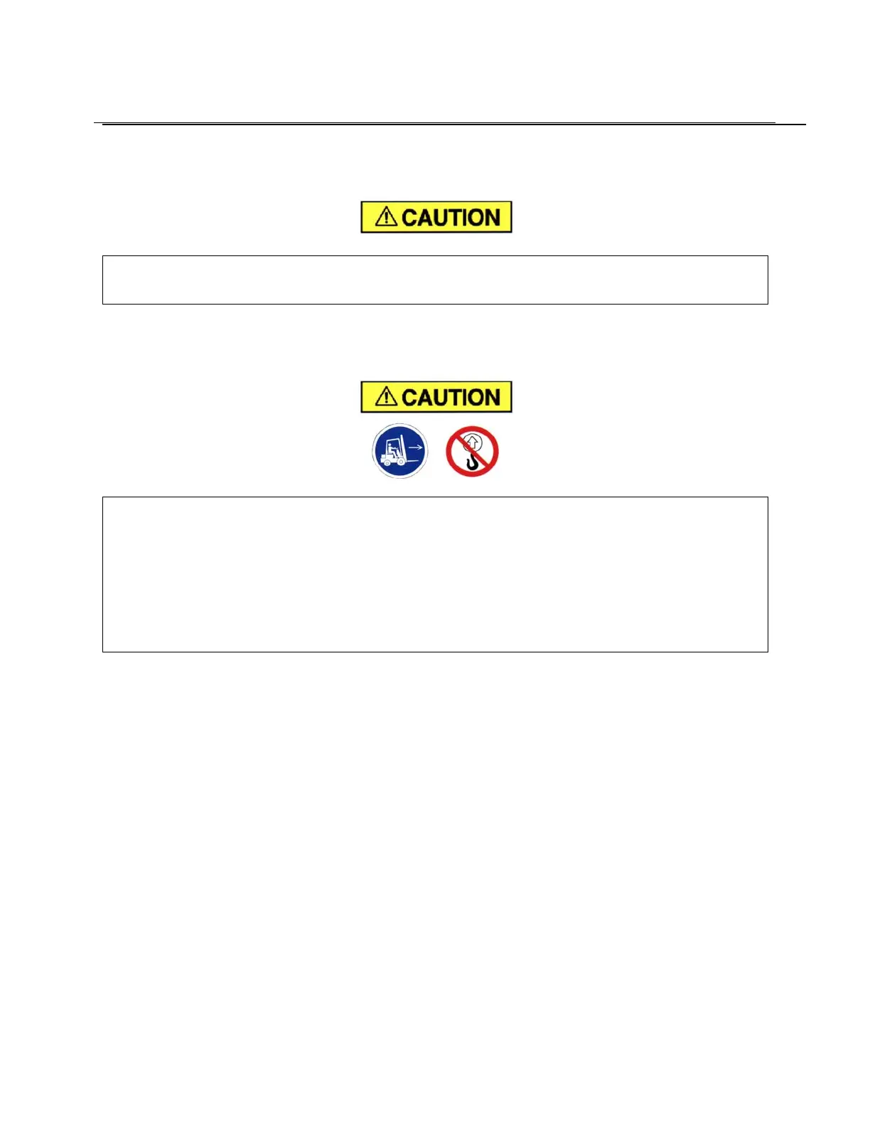
LIFTING UNIT - Proper lifting and/or transporting methods must be used to prevent damage. Unit may
be moved into location by lift truck.
Lift compressor unit by base only. Do not use other places such as motor,
compressor or discharge manifold piping as lifting points.
The eyebolts or lugs provided on the motor are for lifting the motor only and
should not be used to lift any additional weight. All eyebolts must be securely
tightened. When lifting the motor the lifting angle must not exceed 15 degrees.
Failure to observe this warning may result in damage to equipment or personal
injury.
LOCATION (Figure 2-1, page 12) - The compressor should be installed where it is protected from rain,
snow and freezing temperatures, in a clean, well-lighted, well-ventilated area with ample space all
around, including above, for maintenance. If a low ceiling is encountered, the hot discharge air may need
to be ducted out to avoid recirculation. Select a location that provides a cool, clean, dry source of air. In
some cases it may be necessary to install the air filter at some distance from the compressor to obtain
proper air supply.
AIR-COOLED UNIT - A combination oil/aftercooler is supplied as standard equipment on all air-cooled
units. The air-cooled unit with the standard enclosure requires sufficient flow for the compressor
oil/aftercooling system and electric motor cooling (Figure 1-2, page 10). Air is drawn into the unit above
the motor and discharged through the cooler. Do not block the air flow to and from the unit. Allow three
and one half (3-1/2) feet to the nearest obstruction on the control box end of the unit. Allow two (2) feet to
the nearest obstruction above and on other sides of unit.
For continuous efficiency, oil cooler cores must be periodically cleaned with either vacuum or compressed
air. If wet cleaning is required, shield motor and spray on a mild soap solution and flush with clean water.