G1000 / GFC 700 System Maintenance Manual - 300/B300 Series King Air Page 3-9
190-00716-01 Revision 1
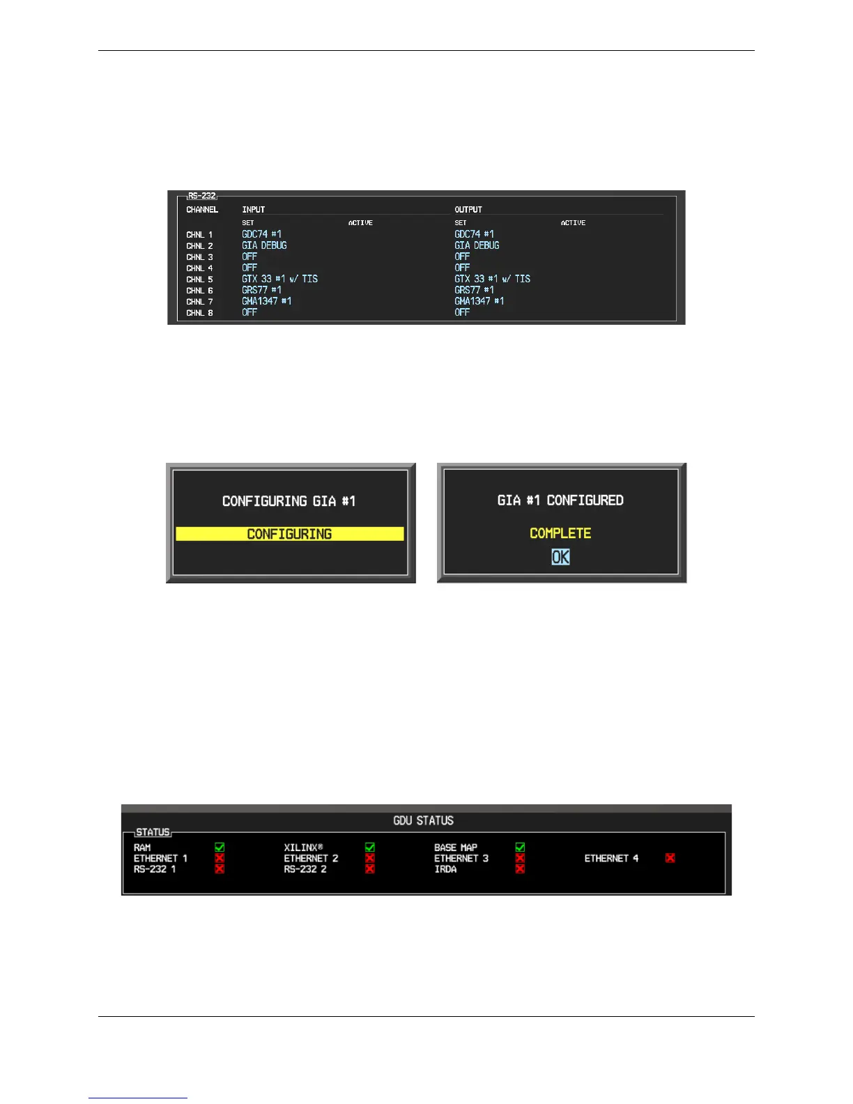
When troubleshooting the system, technicians can look for inequalities between SET and ACTIVE
columns. Certain problems can be resolved simply by pressing the SET>ACTV softkey, which reloads
settings to the specific LRU from the PFD. (Note that this can also be accomplished by reloading the
configuration files for the LRU. Section 7 describes this process for each LRU).
A blank active column, as shown in Figure 3-11, represents loss of communication between the display
and the particular unit. See Section 5 for more details on troubleshooting.
Figure 3-11, Loss of Communication
3.7.2 Configuration Prompts
When configuration settings are changed, the technician receives on-screen prompts and/or confirmations
such as those shown in Figure 3-12. Section 7 shows other prompts encountered during the configuration
process.
Figure 3-12, Configuration Status
3.7.3 Data Transmission Indicators
Several configuration screens utilize an indicator light system to show discrete (ON/OFF) data and/or
hardware component status. Unless otherwise noted, the following applies to all such status indicators:
• Green Checkmark: Expected data is successfully received and is ON. A green check could also
indicate that the parameter/component is working correctly.
• Red X: Expected data is not received. A red X could also indicate that a parameter/component is
invalid.
• White N/A: Expected data is OFF, or no data is expected.
Figure 3-13, Data Transmission Indicators



 To Next Page