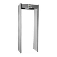
CS 5000
User Manual
© 2009 GARRETT METAL DETECTORS 42 PN 1530100 REV H
7. ReconnectthePowerSupplyModuleandBatteryPackModuleasshown;
8. Reassemble the system and test.
11.7 OPTIONAL STABILIZER BASE INSTALLATION (P/N 1603900)
TOOLS REQUIRED PARTS LIST
•1/4”ElectricDrillMotor •2-MountingPlate
•1/4”(6mm)NutDriverorHexSocket •4-Screw#8x2”Self-Tapping1/4”
•TapeMeasure •1-DrillBit3/32”
•#2PhillipsScrewdriver •1-InstructionSheet
11.7.1 Examine the location and determine the best routing for the power cord.
11.7.2 For each panel, remove and discard the two (2) rubber bumpers located on the bottom of the
panels. these holes will be used for attaching mounting plates to panels.
11.7.3 Using the supplied 3/32” (2.3mm) drill bit, extend the depth of the mounting holes to 2”
(50mm) deep.
11.7.4 Attach the plates (with the edges pointing away from the panel using the supplied 2” long screws.
CAUTION:
The power cord must be installed in the correct Panel location (see Page 8, 3.2.2) before the plate
can be secured. DO NOT PINCH the cord between the panel and the plate. Ensure that the head of
the screw is tight against the plate to prevent the panels from sliding.
11.7.5 Assemble the unit.
11.7.6 Place unit in upright position at selected operating location.